The reason why composite construction is often so efficient can be expressed in one simple way - concrete is good in compression and steel is good in tension. Structurally, when these two materials work together then their strengths can be exploited to result in a highly efficient and lightweight design. The reduced self-weight of composite elements has a knock-on effect by reducing the forces in those elements supporting them, including the foundations. Composite construction is robust and does not require tight tolerances, making the system quick to construct. The floor depth reductions that can be achieved using composite construction can also provide significant benefits in terms of the costs of services and the building envelope.
The scope of this article is to cover a number of different basic types of composite beams, composite slabs, composite columns and composite connections.
Design of composite elements and systems
Design of composite beams in the UK was traditionally carried out to BS 5950-3-1[1]. Composite slabs with profiled steel sheeting were designed to BS 5950-4[2] and the profiled decking used for those slabs to BS 5950-6[3]. There was no British Standards guidance for composite columns. Design of composite beams and composite slabs (for buildings) is now covered by BS EN 1994-1-1[4]. BS 5950-6[3] has been superseded by BS EN 1993-1-3[5]
More information on the relative status of the structural Eurocodes and the British Standards can be found by following the link here.
How composite construction works
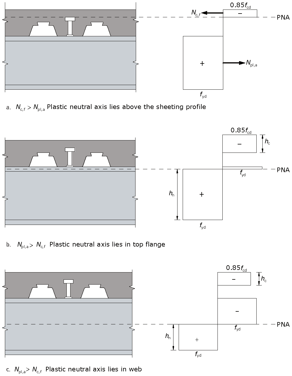
Typical plastic stress distributions for composite beams with full shear connection are shown. For a typical secondary beam, more concrete compression resistance is available than can be employed and the plastic neutral axis (PNA) lies above the sheeting profile. For a typical primary beam, it may be found that the steel section offers more tension resistance than the concrete flange can match in compression resistance. As such the plastic neutral axis lies either in the top flange of the steel section or in its web.
Concrete is a material that works well in compression but has negligible resistance in tension. Hence for structural purposes it relies on steel reinforcement to carry any tensile forces (this is the role played by the steel part in composite construction, which is effectively external reinforcement), or must be pre-stressed so that even when subject to tension, an element is in net compression.
In exceptional circumstances through deck welding is avoided by using single span lengths of decking (which butt up to rows of studs welded directly to the top flange in the fabrication shop), or cutting holes in the decking so that it can be dropped over the shop welded studs.
Other forms of shear connection are available, including larger diameter studs and shot-fired connectors, but for buildings by far the most common option is 19 mm diameter headed studs. Their resistance according to BS EN 1994[4], when used with transverse decking is less than the resistance given in BS 5950-3-1[1]. Also, BS EN 1994[4] states that not more than two studs can be used per trough when the decking runs transverse to the beam axis.
One of the advantages of welded studs is that they are considered to be ductile, which means that (in the absence of any fatigue considerations) the shear connection can be designed using plastic principles because it is assumed that force can be redistributed between adjacent studs. This greatly simplifies the design process.
When a beam is designed with full shear connection it means that sufficient connectors are present to either fully fail the concrete in compression, or fully fail the steel section in tension (whichever is the smaller force). Reduced numbers of connectors may however be used, resulting in so called partial shear connection. However, codes also specify a certain minimum degree of connection that is needed to prevent excessive slip between the steel and concrete, which would result in failure of the connectors. The most common composite beam design is with partial shear connection. For secondary beams and transverse decking this is often the case, as there is not enough space in the available troughs to insert an adequate number of shear studs to achieve full shear connection.
Until it was amended in 2010, BS 5950-3-1[1], which was written in the 1980s, took a fairly simplistic approach to the issue of minimum degree of shear connection. BS EN 1994[4] recognises two additional parameters that influence this minimum degree, namely steel grade and the effect of asymmetry when one of the beam flanges is larger than the other (a smaller top flange is often used as the concrete carries most of the compression, but such asymmetry places higher demands, in terms of slip capacity, on the shear studs). For S275 steel and symmetric sections the limits in BS EN 1994[4] are considerably less onerous than those found in BS5950[1]. For asymmetric beams they are considerably more onerous. In terms of minimum degree of shear connection, even BS EN 1994[4] fails to recognise the considerable benefits when the beam is unpropped during construction, as most are. It also fails to explicitly recognize the benefits to be had when the beam has regularly spaced large web openings, or is only part utilized in bending (because SLS considerations govern design). SCI P405, published by SCI in 2015 as a replacement for NCCI produced by SCI (Pn002a ) allows the minimum degree of connection to be relaxed when certain criteria are satisfied. These criteria assume that the applied loading is at a low enough level, for example, in the common cases where a beam design is governed by construction stage or serviceability considerations.
The benefit of joining the steel and concrete together structurally is to increase the resistance of the steel beam alone; typically this will be by around a factor of two. The stiffness may increase by up to a factor of three. The relative benefits decrease with span, as the size of the steel beam increases relative to the size of the slab.
(Image courtesy of Structural Metal Decks Ltd.)
Types of composite beam
Three general types of composite beam are considered below. The drivers that are relevant to a particular project will affect which flooring system is the most appropriate.
Downstand beams
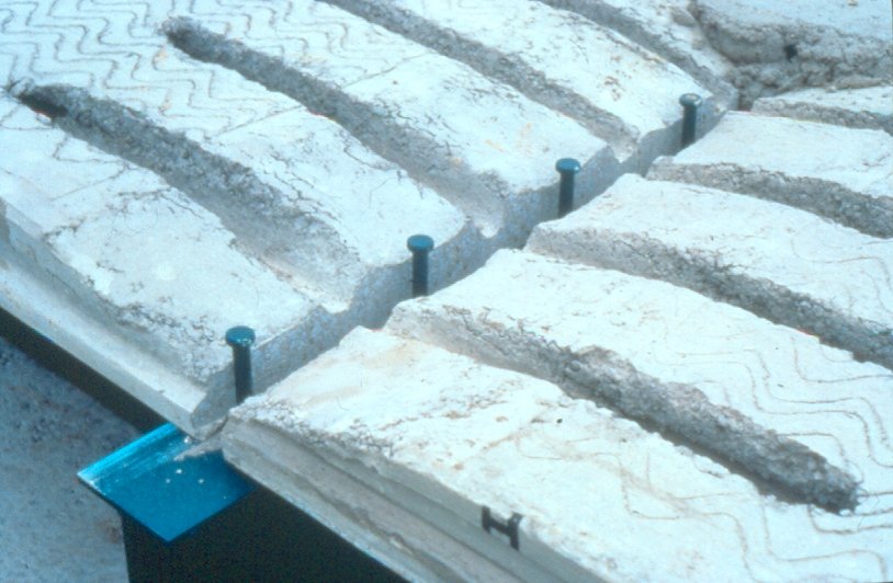
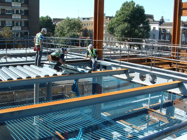
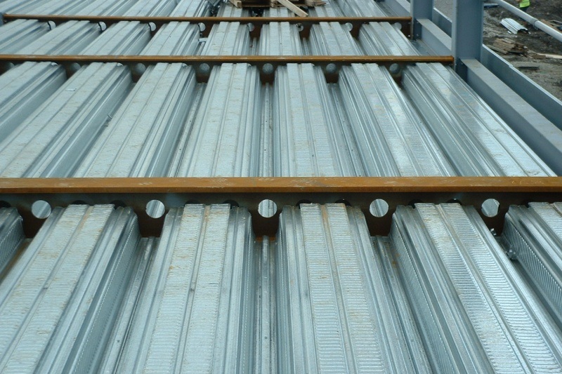
The most common type of composite beam is one where a composite slab sits on top of a downstand beam, connected by the use of through deck welded shear studs. This form of construction offers a number of advantages - the decking acts as external reinforcement at the composite stage, and during the construction stage as formwork and a working platform. It may also provide lateral restraint to the beams during construction, once the decking is fixed into place. The decking is lifted into place in bundles, which are then distributed across the floor area by hand. This dramatically reduces the crane lifts when compared with a precast based alternative.
Further guidance on practical aspects of decking placement may be found in the best practice guide SCI P300.
Another common type of composite beam is one where, as with a traditional non-composite steel framed solution, a precast concrete slab sits on top of the top flange of the steel beam. The effective span range for this type of solution is around 6 to 12 m, which therefore makes it a competitor to a number of concrete flooring options. Particular detailing is required for the shear connection when precast units are used, so that the body of the precast units can be mobilised as part of the concrete compression flange. See SCI P401 for more information.
Long span solutions
A number of variations on the idea of downstand beams are available to meet long-span needs. They provide the opportunity to achieve longer spans (20 m or more) than are possible using a 'standard' solid web, rolled downstand beam.
Shallow floor solutions
![The [https://www.kloecknermetalsuk.com/westok/products/ultra-shallow-floor-beam/ USFB] system <br>''(Image courtesy of Kloeckner Metals UK Westok)''](/upload/Wiki-Files/e/ef/2d35b1fa-e9fc-4477-9dd2-4075a78df478.jpg)
(Image courtesy of Kloeckner Metals UK Westok)
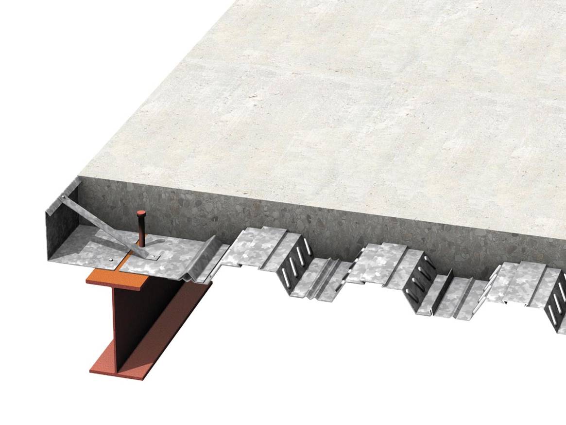
The shallowness of the floors is achieved by placing the slabs and beams within the same zone. This is achieved by using asymmetric steel beams with a wider bottom than top flange, which enables the slab to sit on the upper surface of the bottom flange with adequate bearing, rather than the upper surface of the top flange as found with downstand beams. The floor slab may be in the form of a precast concrete slab or a composite slab with metal decking (either shallow or deep decking may be used). An added benefit is that some forms of shallow floor construction inherently achieve composite interaction between the beams and slab, thereby enhancing structural efficiency.
A number of shallow floor solutions are available, including Ultra Shallow Floor Beams (USFB) from Kloeckner Metals UK Westok, and ArcelorMittal's Slim Floor solutions.
Kloeckner Metals UK Westok’s USFB system comprises a shallow and asymmetric Westok cellular beam with reinforcement placed through the cells to anchor the slab to the beam. ‘Plug Composite Action’ can be mobilised for USFBs, which has been demonstrated using full-scale laboratory testing, to further enhance the capacity of the section. To mobilise ‘Plug Composite Action’, the following detailing should be adopted:
*Composite slabs with metal decking: Concrete cast level with, or above, the top flange
- Precast units generally: Minimum 50 mm topping level with, or with at least 30 mm cover above the top flange
- Hollowcore units: Every 2nd core broken out and filled with concrete and reinforced through the cell
- Solid in-situ slabs: Concrete cast level with (or above) the top flange.
USFBs can economically span up to 10 m with structural depths that compare very favourably with R.C. flat slabs. As such, they are popular in many sectors, particularly Education, Commercial and Residential.

(Image courtesy of Kloeckner Metals UK Westok)
(Image courtesy of Kloeckner Metals UK Westok)
Composite slabs
Composite slabs comprise reinforced concrete cast on top of profiled steel decking, which acts as formwork during construction and external reinforcement at the final stage. The decking may be either re-entrant or trapezoidal, as shown below. Trapezoidal decking may be over 200 mm deep, in which case it is known as deep decking. Additional reinforcing bars may be placed in the decking troughs, particularly for deep decking. They are sometimes required in shallow decking when heavy loads are combined with high periods of fire resistance. Bars in troughs are also a requirement for single spanning slabs and decks designed as single spanning to ensure continuity and ductile failure in fire design.


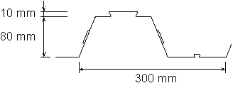
The figure below shows the geometry of a typical 80 mm trapezoidal deck. The steel is galvanized and may be of varying thickness, although about 1 mm is typical. Because it is so thin, there is a need for stiffeners to avoid local buckling when it is acting as a bare steel section to support the wet weight of concrete and other construction loads. The re-entrant stiffener shown at the top of the decking not only stiffens the upper flange but can also be used to support hangers for relatively lightweight items suspended from the soffit. Interlock is achieved through embossments (dimples) that are rolled into the decking profile, and by trapping the concrete around the re-entrant parts of the profile. There are no standard decking profiles, so the interaction achieved by the embossments, etc. of each propriety deck is different. It is determined by tests undertaken by the deck manufacturer.
The profiled decking is often designed to be continuous over two spans when acting as formwork. Composite slabs are normally designed to be simple spanning at room temperature, but continuous under fire conditions. This continuity is achieved thanks to nominal reinforcement, which also fulfils other roles such as crack control, that continues over intermediate supports (its influence - assumed to be beneficial - is ignored for room temperature design).
Re-entrant or trapezoidal decking of 50 to 60 mm depth can span around 3 m unpropped, 80 mm deep trapezoidal profiles can span up to around 4.5 m unpropped, and deep decking can achieve around 6 m. Overall slab depths range from 130 mm upwards. Two hours fire resistance can be achieved without the need to fire protect the steel decking.
It is possible to form openings in composite slabs, although this should be planned and the openings formed at the construction stage rather than having to cut out concrete. Openings up to 300 mm square require no additional provisions, those up to 700 mm require additional reinforcement locally around the opening, and those in excess of 700 mm require the use of trimming steel to support the opening.
Further guidance on the design and detailing of composite slabs is given in SCI P359 and SCI P300 respectively, fire design to the Eurocodes is discussed in SCI P375, and guidance on the installation of metal decking is also available.
Composite columns
Composite columns may take a range of forms, as shown in the figure below. As with all composite elements they are attractive because they play to the relative strengths of both steel and concrete. This can result in a high resistance for a relatively small cross sectional area, thereby maximising useable floor space. They also exhibit particularly good performance in fire conditions.
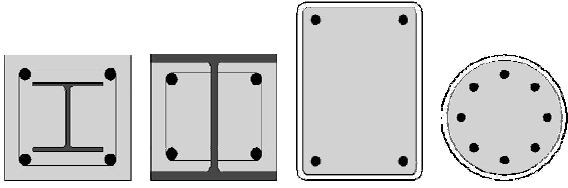
Concrete filled hollow section compression members need no formwork and they use material more efficiently than an equivalent H-section. Concrete infill adds significantly to the compression resistance of the bare steel section by sharing the load and preventing the steel from buckling locally. The gain in fire resistance may be at least as valuable, especially if it permits the column to be left unprotected or only lightly protected. Infill concrete retains free water which in other situations would be lost; its latent heat of evaporation significantly delays temperature rise.
Rectangular and circular hollow sections can be used. Rectangular sections have the advantage of flat faces for end plate beam-to-column connections (using Flowdrill or Hollo-bolt connections). Ordinary fin plates can be employed with either shape.
A programme, FireSoft, for the design of concrete filled hollow sections in ambient and fire conditions has been developed.
Composite connections
Although design guidance exists for composite connections (SCI P213 ), they have been very little used in the UK (or indeed elsewhere in Europe). In theory they appear to be attractive, as slab reinforcement can be used to avoid the need to add to the steelwork connection, for example with extra rows of bolts in an extended end plate. However, it is difficult to achieve the correct detailing for composite connections, because the needs for strength, stiffness and ductility can border on the mutually exclusive - too little reinforcement will reduce connection ductility (rotation capacity) because of potential rebar failure, too much will reduce ductility because of concrete crushing failure.
In an effort to overcome some of the practical issues, so that the inherently attractive features of composite connections can be more widely exploited, research work is on-going in Europe and may result in the inclusion of specific guidance in a revised version of BS EN 1994-1-1[4] planned for around 2025.
Further reading
- Steel Designers' Manual 7th Edition. Editors B Davison & G W Owens. The Steel Construction Institute 2012, Chapters 21, 22 and 23
- Johnson R.P, Composite structures of steel and concrete, volume 1 2004 Blackwell Scientific Press.
- Johnson R.P, Designers' guide to Eurocode 4 Design of Composite Buildings, 2nd edition. ICE.
- Nethercot, D. Composite Construction. Spon Press.
Resources
- SCI P300, Composite Slabs and Beams using Steel Decking: Good Practice for Design and Construction, (3<sup>rd</sup> Edition), 2023
- SCI P359, Composite Design of Steel Framed Buildings, 2011
- SCI P213 Joints in steel construction: Composite connections, 1998
- SCI P287, Design of Composite Beams using Precast Concrete, 2003 (An updated Eurocode version of this publication, P401, is available from SCI)
- PN002a, NCCI: Modified limitation on partial shear connection in beams for buildings SCI
- SCI P365, Steel Building Design: Medium Rise Braced Frames, 2009
- SCI P375, Fire Resistance Design of Steel Framed Buildings, 2012
- SCI P401, Design of composite beams using precast concrete slabs in accordance with Eurocode 4, available from SCI
- SCI P405, Minimum degree of shear connection rules for UK construction to Eurocode 4, 2015
Member design tools: