(Image courtesy of Kloeckner Metals UK Westok)
Generally long spans result in flexible, column-free internal spaces, reduce substructure costs, and reduce steel erection times. This broad range of benefits means that they are commonly found a wide range of building types. The particular advantages and disadvantages of each individual solution are summarised below, so that a designer can assess the benefits offered by a particular solution in relation to the drivers for a given project, to identify the most appropriate and cost effective solution.
Design of long span beams
The use of long span beams results in a range of benefits, including flexible, column-free internal spaces, reduced foundation costs, and reduced steel erection times. Many long span solutions are also well adapted to facilitate the integration of services without increasing the overall floor depth.
The design of long span steel and (steel-concrete) composite beams is generally carried out in accordance with BS 5950[1], BS EN 1993[2] or BS EN 1994[3]. For some types of beam this codified guidance is complemented by specific design guidance, such as that on the design of beams with large web openings (see SCI P355 ), or manufacturers' information. Such specific guidance is normally based on extensive testing of a given product, and often presented in the form of design software.
Long span beam options
The solutions described below are presented in order of increasing spanning ability, with some overlap between options. The aim is to present a wide range of solutions. By far the most common types of beam used today are plate girders, and beams with web openings (be they cellular , fabricated, or rolled sections). Many solutions exploit the benefits of composite construction , which offers considerable strength and stiffness increases over a bare steel alternative.
Parallel beam approach
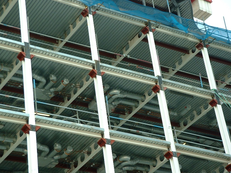
The figure on the left shows a composite floor using the parallel beam approach. Specific guidance on the design of this form of construction is given in SCI P074 . This is based on BS 5950[1] but the principles may be equally applied to a Eurocode design.
Composite beams with web openings
(Image courtesy of FABSEC Ltd.)
A particular type of composite beam with web openings is the so-called cellular beam, which is formed in a specific way and therefore described separately below . The alternative way of forming the web openings is simply to cut them into the plate used to form the web of a plate girder, or into the web of a rolled section. The most appropriate solution to adopt depends on the size, shape and regularity of the openings, or more commercial drivers such as the method used by a preferred supplier. Beams with web openings present no disadvantages in terms of erection and familiarity as they are much the same as a 'standard' solid web beam.
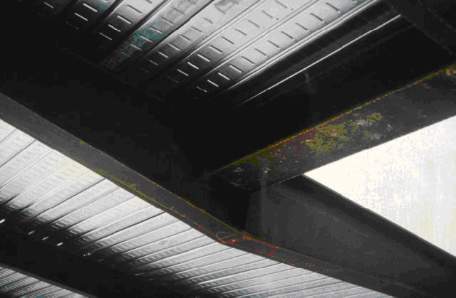
The design of beams with web openings must recognise the fact that the openings introduce a number of potential failure modes not found in solid web beams. Around the openings the beam behaves as a Vierendeel girder, and web post buckling may govern design (the web post is the section of web found between two adjacent openings, as shown in the figure below). Large openings may require stiffening to avoid instability (buckling) of the web posts.
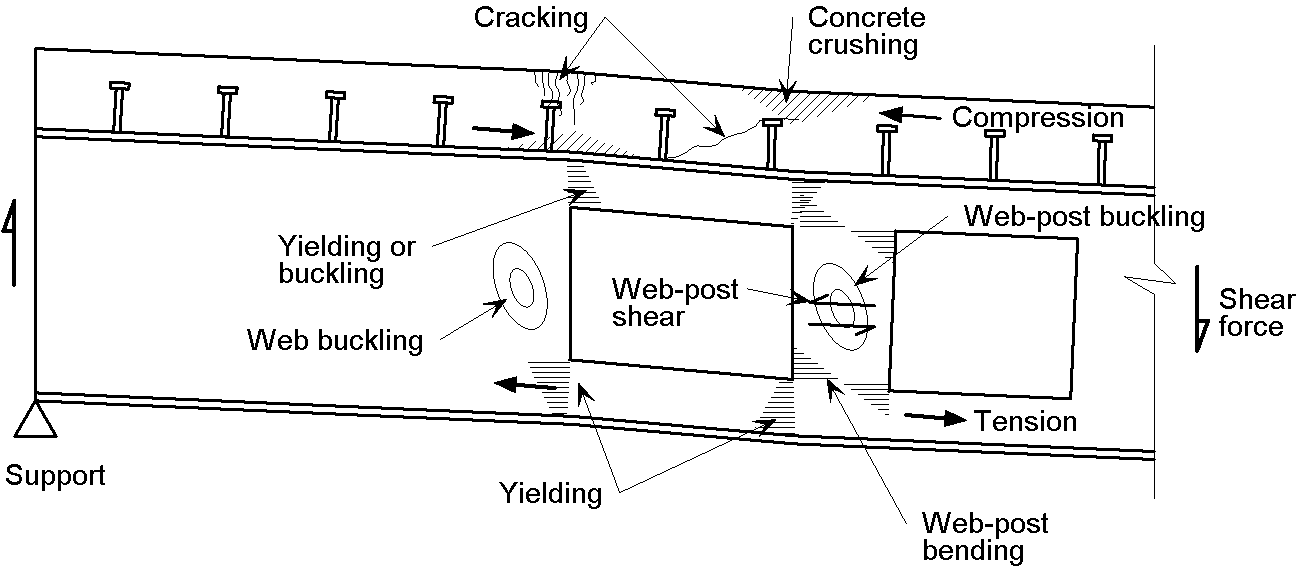
Modes of failure at large closely spaced openings
Composite beam with stiffened web openings
(Image courtesy of FABSEC Ltd.)
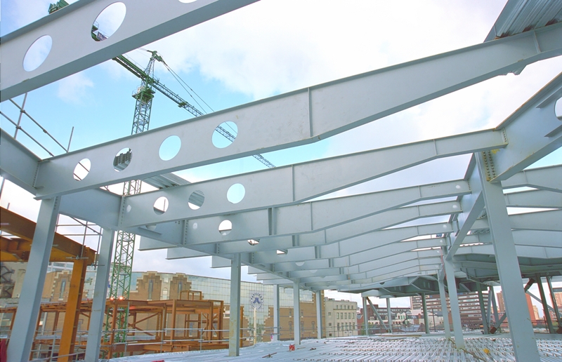
The figure above right shows a composite plate girder with stiffened web openings. Dedicated design guidance (SCI P355) and software from specialist manufacturers is available, based on extensive test programmes that have included fire testing.
Cellular composite beams
BS EN 1994[4] provides design rules to cover beams with an asymmetry (area of the bottom steel flange divided by that of the upper flange) of up to three. The greater the asymmetry the more onerous the requirements for minimum degree of shear connection, which must be observed to prevent excessive slip between the steel and concrete elements.
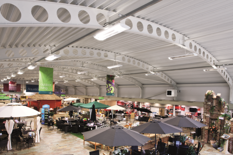
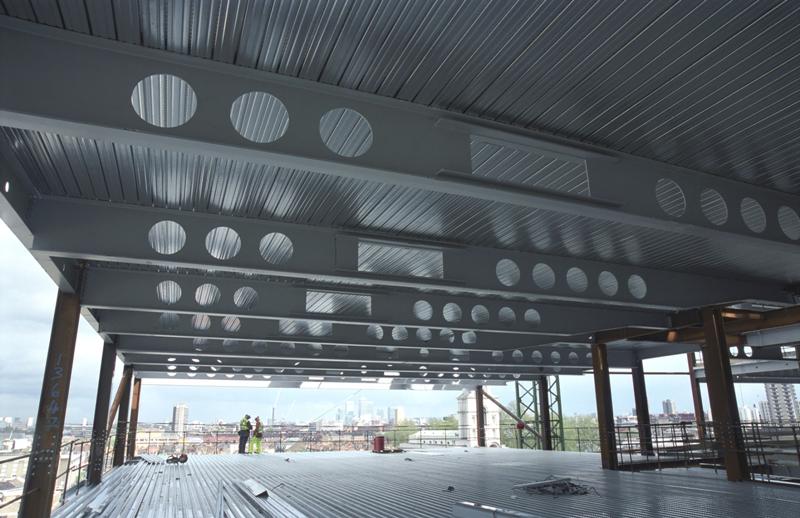
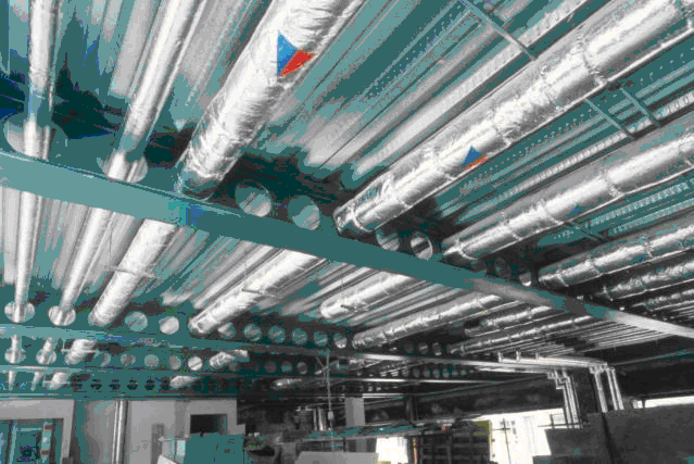
Although cellular beams have regular openings, some of these may be infilled, and/or stiffening added to accommodate local features such as incoming beams or heavy point loads. Double (oval) openings may also be included to facilitate the passage of larger service ducts. Dedicated design guidance (SCI P355 ) and software is available from specialist manufacturers, based on extensive test programmes that have included fire testing. The figure below shows a cellular beam, with regular circular web openings, and services sharing a common floor zone.
Tapered girders
Tapered girders can be a cost effective solution in the span range 10 m to 20 m. They are another solution that allows services to be accommodated within the structural floor zone. The depth of the girder increases towards mid-span, where applied moments are greatest, and thereby facilitating hanging services under the shallower regions near the beam supports. It is also possible to form web openings in tapered girders in regions of low shear, towards mid-span. These provide more options for service integration .Detailed design guidance is available in SCI P059 . Although this is based on design to BS 5950[1], the principles are readily transferrable to a Eurocode based approach.
Tapered girder supporting steel decking
Tapered cellular girder
(Image courtesy of FABSEC Ltd.)
Stub girders
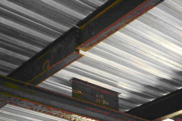
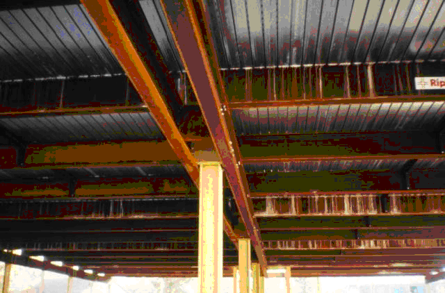
A big advantage of this option is that spans in excess of 20 m can be economically achieved. Services and/or secondary beams can pass through the gaps between the beam stubs, reducing overall construction depth. The figure on the right shows a composite stub girder supporting a secondary beam, which is in turn supporting a composite slab.
Haunched composite beams
Haunches may be added at the ends of a composite beam to provide moment continuity. The stiffness and strength of the connections mean that the rest of the span can be shallower (the bending moment diagram is 'lifted' and the effective stiffness of the beam substantially increased), and services passed under it. In buildings where the services are likely to need frequent replacement (for example in hospitals ), hanging the services under the beams rather than passing them through holes in the webs, or through a truss, can be advantageous. Spans in excess of 20 m can readily be achieved.
Detailed design guidance is available in SCI P060. Although this is based on design to BS 5950[1], the principles are readily transferrable to a Eurocode based approach.
Composite trusses
Composite trusses, which use the concrete slab as the upper chord in the final state, can achieve spans in excess of 20 m. This means they have been used when very long spanning capability was needed. The main disadvantages are that during the construction phase the truss may be rather flexible (laterally), and that in the final state the costs of fire protection can be high given the large number of surfaces to protect. Clearly one of the prices to pay for the spanning ability is that fabrication cost is higher than for a plain beam. Services can be passed through the gaps between the truss members to reduce overall floor depth.
Further reading
- Steel Designers' Manual 7th Edition. Editors B Davison & G W Owens. The Steel Construction Institute 2012, Chapters 18 and 20