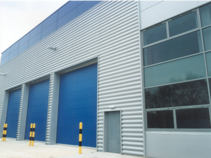
Metal cladding systems provide an efficient, attractive and reliable solution to the building envelope needs of single storey buildings. Over the years, these systems have evolved from the single skin metal cladding often associated with agricultural buildings to highly developed systems used in industrial, retail and leisure applications. However, as with all construction components, the ability of the building envelope to satisfy its functional requirements is dependent on its correct specification and installation and, equally as important, on its interaction with the other elements of the building envelope and structure.
This article explains metal envelope systems and how they are designed, specified and procured.
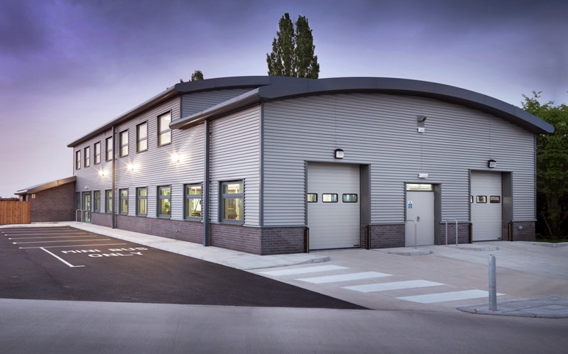
(Image courtesy of A C Bacon Ltd)
The function of the building envelope
All buildings, whatever their use, must provide a controlled internal environment that is protected from the variable and uncontrollable external climate. The requirements of the internal environment will depend on the intended use of the building and this will naturally determine the requirements for the building envelope.
Generating and maintaining a controlled internal environment is a complex process, requiring a combination of mechanical and electrical services to heat and/or cool the building and a well designed building envelope to regulate heat gains and losses. The design of the building envelope is an important factor in specifying the Mechanical and Electrical (M&E) plant and in determining the energy performance of the building. With pressure to reduce operational energy consumption now being placed on the construction industry, the building envelope has never before been under such close scrutiny.
An important requirement of the building envelope is also to provide adequate security. This is particularly the case for large distribution warehouses which can contain goods worth millions of pounds.
In addition to forming the building envelope, the roof and wall cladding may also have an important role to play in the structural performance of the building, by providing restraint to the secondary steelwork against lateral torsional instability. Where such restraint is assumed (as is often the case in the purlin and side rail manufacturers’ load/span tables), it is essential that the cladding is capable of providing this restraint in practice.
In addition to satisfying the functional requirements, the aesthetics of the building envelope is an important issue as the buildings appearance will need to reflect its location and the surrounding environment and meet any local planning requirements.
The building envelope
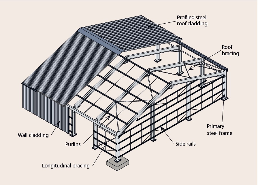
There are essentially three layers to the structure:
- The primary steel frame, consisting of columns, rafters and bracing. The example shown is a portal frame, however, it is equally applicable to other types of structural frames.
- The secondary steelwork, consisting of side rails and purlins for the walls and the roof respectively. These members serve three purposes:
- To support the cladding
- To transfer load from the cladding to the primary steel frame
- To restrain the primary steel frame members
- The roof and wall cladding, whose functions include some or all of the following:
- Separating the enclosed space from the external environment
- Transferring load to the secondary steelwork
- Restraining the secondary steelwork
- Providing thermal insulation
- Providing acoustic insulation
- Preventing fire spread
- Providing an airtight envelope
- Providing ventilation to a building (ventilated or unventilated roofs and walls).
The cladding will also normally include ancillary components such as windows, rooflights, vents and gutters.
As an alternative to the layout shown above, some types of cladding may be installed directly to the primary steelwork without the need for purlins or cladding rails. Examples of this type of construction are deck and membrane for roofs and liner trays for walls. Where such solutions are chosen, the cladding must be designed to:
- Span directly between the rafters, roof beams or trusses. This is usually achieved by the use of deep profiled decks or trays, but where these are insufficient for the required span, intermediate supports in the form of secondary beams or hot rolled purlins will need to be installed.
- Restrain the primary steel members. Structural decks and liner trays, if fastened correctly, should be able to provide sufficient lateral restraint to the outer flange of the supporting rafter or column. Where the outer flange is in compression, the cladding should be sufficient to assure full restraint, although additional members will be required to provide restraint where the inside flange is in compression
Types of metal cladding systems
There are a number of proprietary types of cladding that may be used in single storey buildings, most commonly industrial, warehouse, agricultural and retail buildings. These tend to fall into a few broad categories as described below.
The steel sheet is generally coated with a zinc or zinc aluminium alloy in a hot dip process. The top coating is an organic coating to provide an attractive finish, typically based on Polyvinyl–chloride (PVC or Plastisol), Polyvinylidene–fluoride (PVDF or PVF2), Polyester or Polyurethane formulations. Aluminium cladding sheets are also available.
Steel cladding systems
Manufacture of pre-coated steel products
Single skin trapezoidal sheeting

Built-up double skin cladding
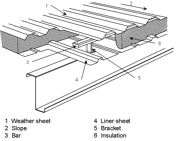
Built-up cladding systems
Liner sheet
The liner sheet serves several purposes:
- It supports the thermal insulation
- It provides an airtight layer
- It provides restraint to the purlins.
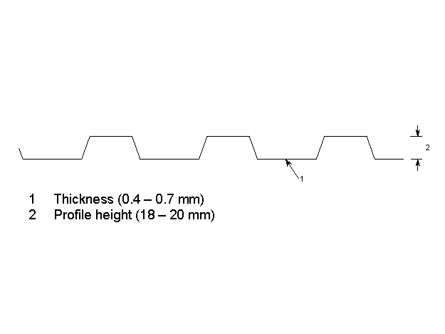
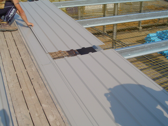
Liner sheets are usually manufactured from cold formed pre-coated steel or aluminium and possess a shallow trapezoidal profile, i.e. a height 18mm to 20mm as illustrated below. For steel liners, the sheet thickness is usually either 0.4mm or 0.7mm, while aluminium liner sheets are slightly thicker at 0.5mm or 0.9mm. The choice of liner will depend on the required spanning capability, the cladding installation method and the acoustic requirements of the cladding. Where required, the acoustic performance of the cladding, in particular its ability to absorb sound and minimise reverberation, may be enhanced by the use of a perforated liner sheet. The shallow liner sheets are not strong enough to walk on, so it is essential that the insulation, spacer system and weather sheet are installed from boards or access platforms, as illustrated below. However, they do provide a non fragile barrier against falling once they have been fully fastened. Where walking access is required, it is common practice to replace the shallow liner profile with a more substantial sheet, i.e. 32mm to 35mm trapezoidal profile in 0.7mm gauge steel.
Insulation
The primary function of the insulation layer is to provide a barrier to the flow of heat between the interior of the building and the external environment. The thickness of the insulation layer in roof and wall assemblies has increased significantly in recent years from approximately 80mm in the 1980s to values approaching 300mm in 2018. Further increases in thickness are possible over the next few years as the regulations on energy use in buildings become more onerous, although it is currently not considered that it is cost effective to go significantly thicker.
The most common form of insulation in built-up cladding systems is mineral wool quilt, which is favoured due to its light weight, low thermal conductivity, ease of handling and relatively low cost. Rigid mineral wool slabs are available, but are less deformable than mineral wool quilts, giving rise to the potential for air gaps between the insulation and the profiled metal sheets. Rigid mineral wool slabs are also much heavier than mineral wool quilts, with consequences for the loading on the supporting steelwork and manual handling on site.
Spacer system

Weather sheet
The outer sheet of a double skin built up cladding system is known as the weather sheet. As the name suggests, its primary function is to protect the building from the exterior climate by forming a weathertight envelope. However, the weather sheet should also be regarded as a structural element, as it plays an important role in transferring externally applied loads, e.g. from wind, snow and foot traffic, through to the other cladding components, secondary steelwork and the primary load bearing frame.
The weather sheets are usually made from either steel or aluminium and are available in a wide variety of finishes and colours. Steel weather sheets are manufactured from pre-coated steel coil. Aluminium weather sheets are available in a mill finish or in a range of painted finishes. Detailed requirements for the weather sheets for roof and wall cladding applications are given in BS EN 14782[1].
Fasteners
A wide range of proprietary fasteners is available which, where required, can be watertight. Most fasteners used for metal cladding applications are both self tapping and self drilling, although screws which are only self tapping are also available for use in pre-drilled holes. Fasteners can be used to connect sheeting to supporting steelwork (or other materials) or to connect adjacent sheets. For most fastener applications, a choice between plated carbon steel and stainless steel (typically grade 1.4301, also known as grade 304, austenitic stainless steel is used) is made. Visible fasteners have the option of factory coloured plastic heads to suit the weather sheet. Further information describing these and other fasteners, e.g. secret fix fasteners, is available in MCRMA Technical Paper No 12[2].
Insulated (composite or sandwich) panels
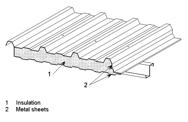
Insulated roof and wall cladding panels consist of a rigid layer of insulation sandwiched between two metal skins, as shown below. The result is a strong, stiff, lightweight panel with good spanning capabilities due to composite action in bending. The panels span between cold formed purlins or side rails, which in turn span between the primary frame members. However, where the secondary steelwork is not needed for restraint purposes, it is quite common for composite wall cladding panels to span directly between the primary framing.
Composite sandwich panels
Standing seam and through fixed systems are available, with either a trapezoidal weather sheet and shallow profiled liner, as shown above, or two flat / micro ribbed sheets. Profiled composite panels are used for roofs to allow rainwater to run off without penetrating the fastener holes, while flat panels are favoured for walls due to their appearance.
Any loads applied in the plane of the cladding (e.g. down slope loads on a pitched roof) are transferred from the external sheet through the two adhesive bonds and the layer of insulation to the internal sheet and the supporting structure. Polyisocyanurate (PIR) is a common insulation material used in foam insulated panels. PIR expands rapidly when sprayed onto the metal profile during production and bonds to it without the need for an adhesive. This property makes it ideally suited to the type of continuous manufacturing process employed by the larger manufacturers of foam filled panels. Alternatively, rigid slabs of mineral wool or other insulating materials, may be bonded to the metal sheets using an adhesive. This method is commonly used for flat faced wall panels.
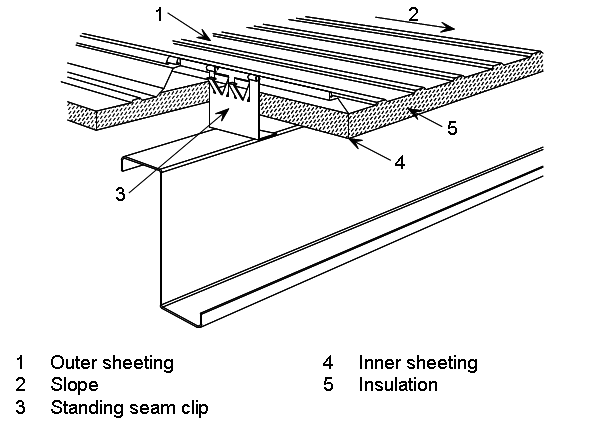
Standing seam systems
Structural liner trays
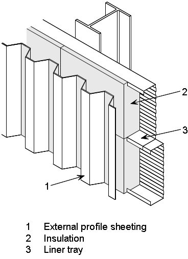
However, consideration should be given to thermal bridging that can exist with liner trays. This issue may be partially overcome by placing an additional layer of rigid insulation on the outside of the tray.
Where plastic design of portal frames is a common design approach, the absence of side rails can create issues when attempting to provide restraint to the inside flange of the columns, e.g. in the hogging region of a portal frame, since traditional knee bracing cannot easily be attached to the liner tray profile.
Structural liner trays can also be specified with perforations where improved acoustic performance is required.
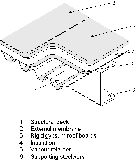
Structural deck and membrane roof systems
Transpired solar collector wall cladding
Wall cladding with an inbuilt transpired solar collector provides a simple, efficient and cost effective solar technology to be incorporated within the building envelope. Transpired solar collectors utilise solar radiation to deliver naturally warmed fresh air into buildings. With no moving parts, minimal energy running costs and minimal CO2 emissions, this technology provides a renewable heat energy source with payback periods of as low as 3 years for new build and 7 years for refurbishment projects.
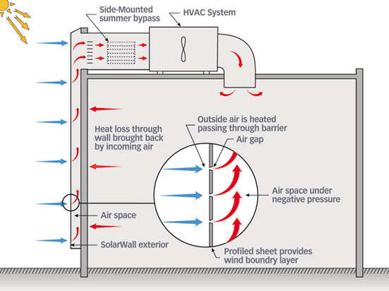
During the heating season, the system collects both solar energy and recaptures wall heat loss. During the cooling season, collector bypass vents can be opened allowing the wall to allow heat to be dissipated, thus reducing cooling loads.
This technology is ideally suited for buildings that have a predominantly south-facing wall with access to the building ventilation system. The collector surface is generally trapezoidal steel or aluminium sheeting and can be any dark colour.
Colorcoat Renew SC® from Tata Steel, and SolarWall® from CA Group are examples of such proprietary systems manufactured in the UK.
Specification of the cladding
The specification of roof and wall cladding has implications well beyond the aesthetics and weathertightness of the building. The choice of cladding can affect many aspects of the building’s performance, from its construction right through to its eventual demolition and disposal. Indeed, the fitness for purpose of the whole building can be compromised if sufficient care is not taken when specifying the cladding. The main factors that should be taken into consideration when specifying profiled metal cladding systems are:
- Weathertightness
- Strength and rigidity
- Thermal insulation
- Control of condensation
- Control of thermal movement
- Sound insulation
- Fire resistance
- Appearance
- Durability
- Cost
- Daylighting
- External attachments
- Lightning protection
- Design detailing
- Maintenance, remedial work and renewal.
- Control of air leakage
Minimum performance requirements for a number of these factors are laid down by legislation. Other factors, such as appearance and daylighting, may not seem to be as critical from an engineering viewpoint, but might be crucial to the success of the building in terms of the well-being of the occupants and the acceptance of the building by the local community. It should not be forgotten that the cost of the insulated cladding in a typical commercial or industrial building is usually a significant proportion of the overall construction cost, so decisions relating to the cladding can strongly influence the economic viability of the project. The cladding also has a significant impact on the operational energy requirements and, therefore, the operating costs of the building in service, specifically heating, cooling and lighting.
Envelope flashings
Weathertightness
The primary function of the cladding system is to provide a weathertight building envelope, suitable for the intended use of the building. With this in mind, the cladding specifier must give careful consideration to the selection of the cladding components and the detailed design of the system. The location of the building, its orientation and the external climate should all be considered when specifying the cladding. The satisfactory performance of the system also depends on the correct assembly of the components in the factory and/or on site.
In general, roofs are at greater risk of rainwater leakage than walls, and this risk increases as the roof pitch decreases. This is an important factor in the design of modern non domestic buildings, since many have low pitch or flat roofs in order to minimise the volume of empty roof space. Not all types of roof cladding are suitable for use on low pitch roofs. Specifiers must, therefore, pay careful attention to the minimum pitch recommended by the manufacturers, together with the published guidance on detailing and installation.
Trapezoidal metal roof sheets with through fix-fasteners are generally suitable for slopes of 4°(7%) or steeper. This 4° limit is critical to the performance of the cladding and should take into account deflections in the supporting steelwork and localised cladding deformations that may lead to ponding. Where the primary steelwork is precambered to off set the deflections due to permanent actions, great care must be taken to ensure that excessive precamber does not result in local high points, as these can also cause ponding. For shallower pitches, down to 1.5° (1.5%), a secret fix system with no exposed through fasteners, special side laps and preferably no end laps should be used. Secret fix systems may also be used on steeper roofs where increased reliability is desired.
For low pitch roofs, ponding is a potential problem that must be considered at the design stage in order to avoid the deleterious effects of prolonged soaking and the increased loading due to the weight of the water. Where ponding occurs on rooflights, there is also the additional problem of dirt deposits as the water evaporates, hindering daylight penetration into the building.
Side and end laps in profiled sheeting are weak points in the building envelope, where the wind and rain could potentially penetrate the cladding. The design and construction of the laps is therefore critical to the weathertightness of the cladding system. End laps typically consist of two continuous butyl sealant strips, which are compressed to form a weathertight seal by the clamping action of the fasteners. The pitch of fasteners required to achieve a proper seal will depend on the profile geometry, but one fastener per trough is common. A typical side lap between trapezoidal sheets is formed by overlapping the profiles with a strip of butyl sealant positioned on the weather side of the fastener to provide a weather resistant seal. The side laps should be stitched at 500mm centres or closer using steel stitcher fasteners. Further information on side and end lap details is given in MCRMA Technical Paper No. 6[5] and Technical Paper No. 16[6]. Reference can also be made to ECCS TC7[4].
Building appearance
- Profile shape
- Colour
- Fasteners.
The profile shape can have a significant impact on the appearance of a building due to its effect on the perceived colour and texture of the cladding (caused by the reflection of light). The orientation of the cladding (ribs horizontal or ribs vertical) will also influence the appearance of the building, due to the effects of shadow and reflection. A potential disadvantage of horizontal ribs is that they tend to suffer from an accumulation of dirt over time, unless the cladding is cleaned regularly. Where the location and function of the building demand a smooth flat exterior, insulated wall panels with flat facing sheets may be used, however, it should be noted that any defect on the surface will be readily noticeable.
The steel from which profiled cladding sheets are made is available pre-coated in a wide range of colours and textures, allowing architects to choose a finish that best suits the location and function of the building. In choosing the finish, the architect should bear in mind the influence of the profile shape on the overall appearance by making an allowance for the effects of reflection and shadow on the perceived shade of colour.
Thermal performance
Energy consumption

A significant proportion of carbon dioxide emissions is related to the operational energy requirements of buildings (heating, lighting, ventilation, etc.). Although many factors influence a building’s energy efficiency, the thermal performance of the building envelope is significant. The main sources of heat loss through the building envelope are shown.
Thermal bridges
Thermal bridges are areas or components within the roof or wall cladding assembly whose thermal insulation properties are lower (often much lower) than those of the surrounding material, thereby permitting local high heat flows through the building envelope. A common example of a thermal bridge would be a metal spacer in a built up cladding system. In general, all metal components will act as thermal bridges, because of their high thermal conductivity, unless specific measures are taken to interrupt the heat flow by introducing a layer of thermal insulation. Thermal bridges increase the heat loss from a building, thereby increasing the operational energy requirement. It can also lead to a reduction in the internal surface temperature of the cladding, causing condensation to form under certain conditions.
Thermal transmittance
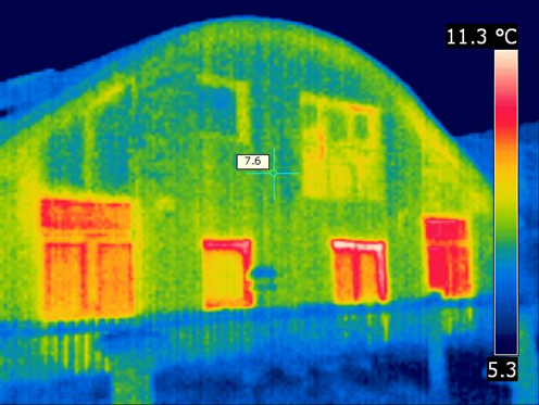
National regulations for thermal performance generally specify maximum U values. These are often the weighted average (or similar “overall” figure) for the whole of the roof or wall, with maximum values for individual elements such as doors. The individual elements tend to have much higher U values than the cladding.
A thermal image of a building demonstrating the relative temperature of different parts of the building façade, i.e. where thermal transmittance is greatest/least, is shown.
Typical limiting U values based on Approved Document Part L – Volume 2 (2021 Edition)[7] are shown in the table.
Over recent years, the drive to improve the energy performance of buildings has resulted in a significant reduction in the U values for building envelope elements, resulting in a corresponding increase in insulation thickness. This has had important implications for the structural performance of the cladding system and its relationship with other structural elements. Of particular concern to the structural engineer are the increased depth and weight of the cladding and its ability to adequately restrain the purlins or side rails. It is likely that this trend will continue however, the diminishing returns obtained from further reductions in U values means that in future more emphasis is likely to be placed on airtightness and the performance of mechanical services, rather than ever increasing insulation thicknesses.
|
Element |
Area weighted average (Wm-2K-1) |
|---|---|
|
Wall |
0.26 |
|
Roof |
0.18/0.16 (flat/pitched) |
|
Window |
1.6 |
|
Pedestrian door |
1.6 |
|
Roof ventilator |
3.0 |
|
Element |
U-value (Wm-2K-1) |
|---|---|
|
Built-up system, 180mm insulation |
0.25 |
|
Built-up system, 210mm insulation |
0.2 |
|
Composite panel, mineral fibre, 120mm |
0.34 |
|
Composite panel, mineral fibre, 150mm |
0.27 |
|
Composite panel, PIR, 60mm |
0.33 |
|
Composite panel, PIR, 100mm |
0.20 |
Airtightness
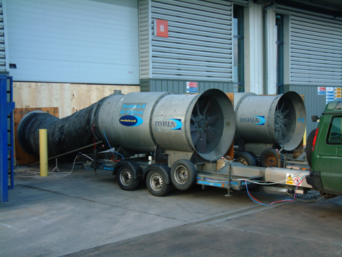
(Image courtesy of BSRIA)
Interstitial condensation
Interstitial condensation occurs within the layers of the cladding construction and is due to warm moist air from within the building penetrating the liner and condensing on the cold outer sheet and other components. The severity of the problem will depend on the relative humidity of the air within the building, the external air temperature and humidity, and on how well the liner is sealed. Buildings in cold climates and those containing swimming pools, laundries or other similar applications are most at risk, as are cladding systems that incorporate a perforated liner and separate vapour control barrier. In extreme cases, the condensation could result in corrosion of steel components within the roof assembly or in wetting of the insulation.
Recommendations for avoiding interstitial condensation are usually given in BS 5250[8].
Acoustics
Depending on the application, acoustic performance can be an important consideration when specifying roof and wall cladding. There are a number of categories of acoustic performance to consider, as illustrated.
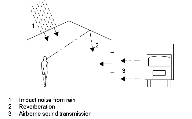
Impact noise
The noise created by the impact of rain or hail on metal roof sheeting can sometimes create a nuisance for the building occupants. Where impact noise is considered to be important, it can sometimes be reduced by placing a flexible insulation layer directly below the outer sheet to act as a damper.
Reverberation
In certain applications, such as offices or residential accommodation, internal acoustic performance might be critical to the functionality of the building. Of particular interest is the reverberation caused by sound waves reflecting off hard internal surfaces, including elements of the building envelope. Typically, the internal finishes of the building will be used to limit reverberation, but architects may also take advantage of the sound absorbing properties of the cladding insulation layer by replacing the standard liner sheet with a perforated liner. Where the envelope consists of insulated sandwich panels, it is not uncommon to install a perforated liner and a layer of mineral wool insulation on the inside of the envelope in order to reduce reverberation.
Airborne sound transmission
Where there is a need to limit the passage of sound through the building envelope, the cladding specifier needs to consider the Sound Reduction Index (SRI) of the cladding. The SRI is a measure of the reduction in sound energy (in decibels) as sound passes through a construction at a given frequency. The acoustic performance of a particular cladding system will depend on the thermal insulation material, the weather sheet and liner sheet profiles and the method of assembly. Of these, the insulation is the dominant factor.
Noise associated with building services equipment
Consideration should also be given to attenuating noise emanating from services equipment and machinery. These include providing sound enclosures for noise prone machinery and/or including equipment supports with dampers. Reduction of noise from services is particularly appropriate in industrial buildings.
It is generally considered that a suitable indoor noise level in industrial buildings is 65dB, whereas 50 to 55dB is considered a suitable indoor ambient noise level for commercial, retail and leisure buildings. For industrial buildings, noise breakout is usually a greater concern. Local regulations may specify acoustic requirements to reduce noise breakout from within a building (for example if the building is sited adjacent to a residential area).
Cladding system manufacturers will be able to provide acoustic performance data for different constructions, and be able to recommend a system to meet the specification.
A built up system comprising an inner and outer sheet of pre finished steel with mineral wool insulation generally achieves over 40dB of sound reduction. Rock mineral wool has a greater density than glass mineral wool, and generally improves the sound insulation. Sound insulation can be improved by including a layer of dense acoustic mineral wool slab, in addition to the insulation quilt.
In general, factory insulated foam filled composite systems are not as effective as built up systems, because of the low mass of the foam core and the direct coupling of the inner and outer skins.
The sound reduction index Rw for various systems is shown in the table below. A higher index indicates higher sound reduction. See MCRMA Technical paper No. 8[9] and ECCS TC7 Publication 41[4].
|
Cladding type |
Sound reduction index Rw (dB) |
|---|---|
|
Built-up system with rock wool and acoustic insulation |
47 |
|
Built-up system with rock wool |
45 |
|
Built-up system with glass mineral wool |
41 |
|
Composite panel with mineral wool |
31 |
|
Composite panel with foam |
25 |
|
Single skin |
24 |
Fire performance
The fire performance requirements differ fundamentally from those relating to thermal performance, durability, weathertightness and acoustics in that fire is an exceptional event, and one from which it is possible that the building will not survive in a serviceable state.
The purpose of the Building Regulations with respect to fire is to ensure the Health and Safety of the occupants and people close to the building, rather than to preserve the building. Consequently, the provisions of Approved Document B[10] aim to provide a safe means of escape for building occupants, allow safe access for the Fire Brigade and prevent the spread of fire to neighbouring properties.
The manufacturers of cladding systems are required to subject their products to rigorous fire tests in order to secure approval from the building insurance organizations. These tests are in accordance with Loss Prevention Council LPS 1181[11] or FM Approvals 4880[12]/4471[13] tests and certification. Specifiers of cladding products should ensure that such approval has been granted for the product under consideration and that it is deemed suitable for the application in question.
Fire design of walls
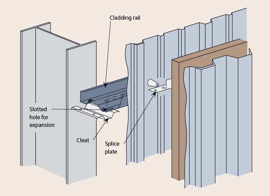
It is often considered necessary to provide slotted holes in the side rail connections to allow for thermal expansion. In order to ensure that this does not compromise the stability of the column by removing the restraint under normal conditions, the slotted holes are fitted with washers made from a material that will melt at high temperatures and allow the side rail to move relative to the column under fire conditions only. An example of this type of detail is shown in the figure below.
Durability
All cladding systems suffer a certain degree of degradation over time due to moisture, atmospheric pollution and UV radiation. However, the cladding specifier can have a considerable influence on the long term performance of the cladding through careful selection of materials and good detailing. Once in service, regular maintenance will prolong the life of the building envelope.
The metal from which the weather sheet is made is available with several types of coating with a wide variety of colours and finishes. Guidance on the expected design lives of these coatings is available from MCRMA Technical paper No. 6[5] and also from ECCS TC7 Publication 41[4]. It is worth noting that the colour of the coating has a significant impact on its design life. Light colours reflect thermal radiation more efficiently than dark colours, resulting in lower surface temperatures and a reduction in the degradation experienced by the coating.
When detailing the building envelope, particular attention should be given to the avoidance of water and dirt traps by specifying suitable slopes and end laps. Careful detailing is needed at the external interfaces to avoid the ingress of water and at the internal interfaces to prevent water vapour from within the building entering the cladding assembly (resulting in interstitial condensation).
In order to ensure that the building envelope remains fully functional throughout its design life, it is important that it receives regular maintenance, including inspection, removal of debris, cleaning and repair of damage. Since maintenance usually involves access by workmen, often carrying equipment, it is essential that this is allowed for in the design of the building envelope and the supporting structure. The need for maintenance may be greatly reduced by specifying a coating for the weathersheet with a ‘maintenance free’ guarantee for the expected design life of the cladding (typically 20 to 30 years). Such coatings can provide significant benefits to the client in terms of whole life costs and improved safety.
Structural performance
Metal cladding systems are required to carry externally applied loads, such as snow and wind loading without deflecting excessively or compromising the other performance requirements. The individual characteristic loads (actions) should be obtained from the appropriate part of BS EN 1991[14], taking into account the building geometry and location as applicable. These individual actions should then be combined using the appropriate safety factors from BS EN 1990[15] to obtain the load cases used in design.
Actions
Permanent actions
For most industrial and commercial applications of metal cladding technology, the only permanent action for which the roof cladding needs to be designed is its own self weight, including the weight of the insulation. Typical weights of insulated panels and built up cladding systems are given in the table . For information on specific cladding products, designers should consult the technical literature available from manufacturers or suppliers. For wall cladding, it is not normally necessary to consider permanent actions, since the self weight acts in the plane of the cladding. However, where a rainscreen system is attached to the outer face of the cladding panel or assembly, it will be necessary to consider the impact of the rainscreen system weight when specifying the fasteners.
|
System |
Insulation |
Depth (mm) |
Sheet thickness (mm) |
Weight (KN/m2) |
|
|---|---|---|---|---|---|
|
Inner |
Outer |
||||
|
Built-up |
Mineral wool |
180 |
0.4 |
0.7 |
0.16 |
|
Built-up |
Mineral wool |
180 |
0.7 |
0.7 |
0.20 |
|
Insulated panels |
PIR |
80 |
0.4 |
0.5 |
0.12 |
Note
The depths presented correspond to a U-value of 0.25 Wm-2K-1 for typical cladding systems using the insulation shown.
Variable actions
In addition to its self weight, the roof cladding must also be designed for the following variable actions as specified in the appropriate parts of BS EN 1991[14].
- Access for cleaning and maintenance
- A uniformly distributed load due to snow over the complete roof area. The value of this load will depend on the building’s location
- Asymmetric snow load and loading due to snow drifts
- Wind loading due to pressure and suction.
Care should be taken when ‘green’ roofs are specified, as they tend to be considerably heavier than traditional metal roofs and, in the case of roof gardens, must be designed for the presence of garden furniture and people, etc.
Wall cladding should be designed for wind loading according to BS EN 1991 Part 1-4[16]. Positive wind pressure and wind suction will need to be considered, with special attention paid to the areas of high wind suction close to the corners of the building. The wind suction design case is often governed by the resistance of the fasteners connecting the cladding panels or sheets to the supporting steelwork.
Deflections
The cladding must be capable of carrying the specified design loads without deflecting excessively, if the other performance requirements such as weathertightness, airtightness and durability are to be achieved. The predicted deflections are normally calculated for the unfactored variable actions only. Loading at the construction stage is not normally included in the serviceability load cases and is not normally considered when specifying cladding systems. However, care must be taken on site to avoid excessive local deflections, especially those caused by concentrated loads such as foot traffic or stacked materials on roof liner sheets, as these could result in permanent damage to the cladding. Typical deflection limits imposed on the cladding are dependent on the loading regime considered (imposed load only or permanent plus imposed loading), the location (wall or roof) of the structural component and whether a brittle material is present. Common deflection limits are:
- Span/150 for wall cladding, spanning between secondary steelwork
- Span/200 for roof cladding, spanning between purlins
- Span/180 for purlins or side rails.
Use of safe load tables
The manufacturers of profiled metal sheeting and insulated panels provide load tables for their products, which may be used either to select a suitable profile or, where the profile has already been chosen, to determine the maximum permissible purlin spacing. It is important to note that the load tables often assume that the loading is uniformly distributed and that safe working loads are usually specified. If in doubt, specifiers should seek guidance from the cladding manufacturers.
Cold rolled secondary steelwork
Purlins and cladding rails
Purlin and side rail options
Purlins and side rails are generally cold formed light gauge galvanized steel members, supplied as part of a proprietary cladding support system, together with fittings, fasteners and other associated components.Section options
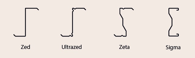
Further information on these sections may be obtained from the manufacturers’ technical literature.
Purlins and side rail layout options
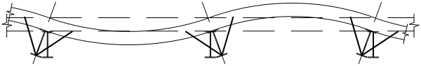
Most manufacturers produce guidance on typical purlins layouts that are efficient for various situations. These layouts are governed by such aspects as maximum length (generally not more than 16m for transport and site access reasons) and the ability to provide semi continuity by the use of sleeves or overlaps for maximum efficiency. The most commonly used layouts are shown below. Specifiers seeking further information on when and how to use a particular layout should consult the purlins manufacturers for detailed information relating to their specific systems. In any event, the purlins and side rails manufacturer should be consulted before the layout is finalised.
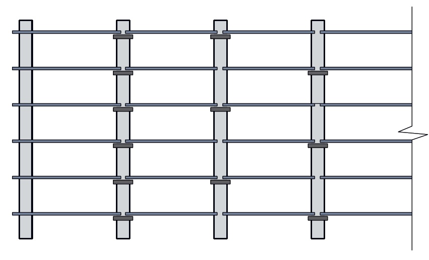
Single span lengths - sleeved system
In sleeved systems, each purlin is the length of a single span but sleeves are provided at alternate supports so that each purlin is effectively continuous across two spans (see below). At the penultimate support, sleeves are provided at each purlin, to provide semi continuity and additional strength in the end bay. This system is considered to be the most efficient for buildings with bay centres between 5m and 7m. Heavier sections can be provided in the end bay if necessary.
Single span lengths - butted system
Single span butted systems have a lower capacity than the other systems, but are simpler to fix either over the rafters or between rafter webs (see below). This layout may be used for small buildings with close frame centres, such as agricultural applications.
Single span lengths - overlapping system
An overlapping system provides greater continuity and can be used for heavy loads and long spans (see above). It is best suited to buildings with a large number of bays.
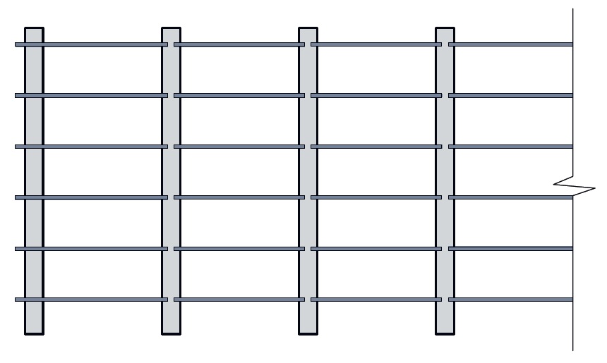
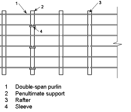
Double span lengths–non sleeved system
In this system, the double span lengths are staggered (see below). Sleeves are provided at the penultimate supports to ensure semi continuity. The capacity will generally be less than for the equivalent double span sleeved system, but double span purlins use fewer components and lead to faster erection. This system is limited to bay sizes less than 8m, for reasons of transport and erection of purlins.
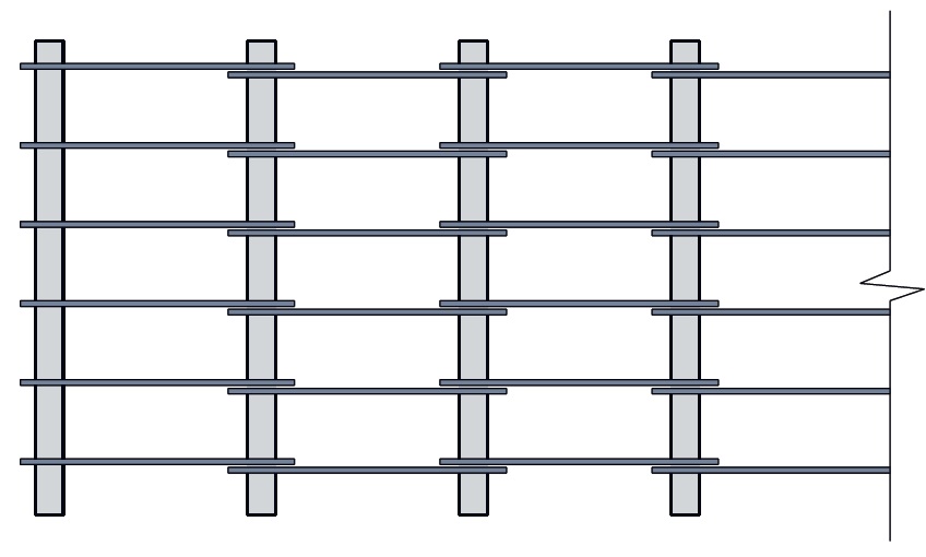
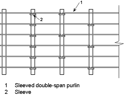
Double span lengths-sleeved system
In double span sleeved systems, the double span lengths are staggered and sleeves are provided at alternate supports (see below). Sleeves are provided to every purlin at the penultimate support to ensure semi continuity. A double span sleeved system has a slightly higher capacity than the double span non sleeved system and has the advantages of semi continuity at all sleeve positions. This system is limited to bay sizes less than 8m, for reasons of transport and erection. Heavier purlins can be provided in the end bays, if necessary.
The use of anti-sag rods for purlins
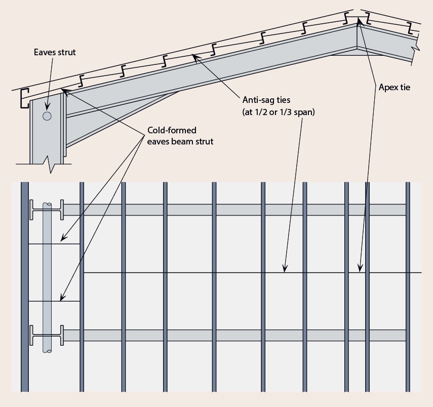
- They provide restraint to the purlin against lateral torsional buckling under wind uplift conditions
- They provide restraint to the purlins in the construction condition (before the installation of the cladding)
- They provide additional support to the downslope component of the applied loads
- They help to maintain the alignment of the purlins.
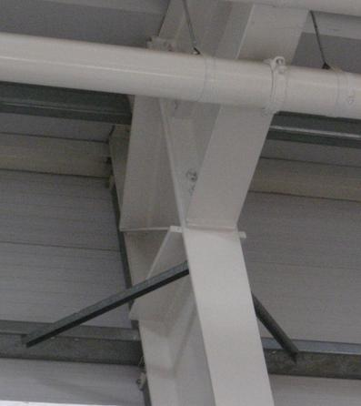
The anti-sag rods are assisted in these functions by eaves beam struts and apex ties, both of which are illustrated in the accompanying image.
The need for anti sag rods is dependent on a number of factors, including the chosen purlin section, the spacing between the purlins, the span of the purlins and the magnitude of the applied loads. Advice on this issue may be obtained from the purlin manufacturers’ technical literature. In some instances, the specifier may have a choice between the use of anti sag rods or the selection of a heavier purlin that does not require intermediate restraint or support. There is clearly a trade off between the cost of a heavier purlin section and the time (and corresponding cost) associated with the installation of additional components.
Anti-sag rods only provide restraint at discrete locations along the span of the purlin. The purlins should only be considered to be ‘fully’ restrained under gravity loading in the finished condition, when continuous restraint is provided to the compression flange by the cladding.
The use of side rail supports for wall cladding
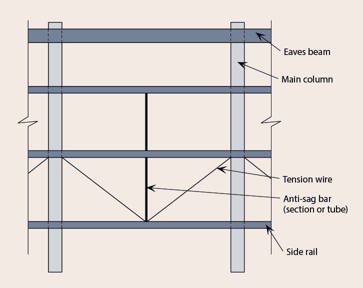
For column spacings up to 6m with a typical side rail spacing of 1.8m, a single central vertical restraint will normally be sufficient. However, for greater column spacings, two or even three vertical restraints may be required. In many cases, the uppermost side rail is connected to the eaves beam. This arrangement will reduce the forces in the tie wires, but the additional force in the eaves beam will need to be considered when this member is sized. It is also worth noting that, once installed, the cladding will stiffen up the wall substructure and transfer a significant proportion of the vertical load to the columns by diaphragm action. The cladding will also fully restrain the side rail against lateral torsional buckling in the sagging case and will provide partial restraint in the hogging case.
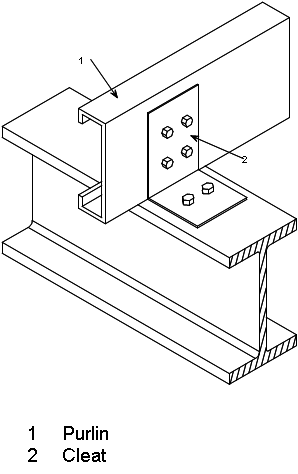
Cleats
Loading
The purlins and cladding rails need to be designed to carry all of the loads applied to them from the cladding and to transfer these loads into the structural frame. These loads will include the permanent actions due to the weight of the cladding and secondary steelwork together with the variable actions. It will usually be acceptable to consider these actions as acting uniformly over the purlins, but account must be taken of high local forces such as the wind suction forces close to the edges of the building. In addition to the cladding loads, the purlins may also be required to support the weight of services or suspended ceilings. The structural engineer responsible for specifying the purlins will frequently play little or no part in the specification of the services or ceilings.
Nevertheless, it is important that an accurate estimate of these loads is obtained together with the nature of the loading (whether concentrated or distributed), since they could form a significant proportion of the overall gravity loading on the purlins. Particular care should be taken where the purlins are required to support concentrated loads. Gutters and their supporting structure require special attention, as the loads associated with them are often very high. Designers need to consider the weight of the gutters plus that of their contents (water or snow). Specific information on the specified gutter system should be sought from the gutter manufacturers.
During the construction stage, the purlins may still be required to carry significant gravity loads (from stacked materials), but without the benefit of any restraint provided by the cladding. The magnitude of the construction load will depend largely on the cladding installation procedure and the materials, plant and labour used.
Deflections
The deflection limits for the purlins and side rails are generally governed by the choice of roof and wall cladding, since the governing factor is the ability of the cladding to deflect without compromising weathertightness, airtightness, robustness or any other performance requirement. In general, the greater the flexibility of the cladding, the larger the allowable purlin or side rail deflection. In this respect, profiled metal cladding systems are far more tolerant of deflections than brittle materials such as masonry. By contrast, windows are often critical and further guidance should be sought from the glazing manufacturers.
Excessive deflection under purlin or rail self weight, or under the action of construction loads prior to the fixing of the cladding, can lead to difficulties for the cladding installation. This should be addressed by careful consideration of the likely construction loading and by specifying a method of cladding installation that avoids overloading the unrestrained purlins. Gutters are especially sensitive to deflections, due to the need to avoid backfalls.
Purlin and side rail selection
The major purlin and cladding rail suppliers have invested heavily over many years in the development and testing of their systems and all publish design guidance and load/span tables for their products. In many cases, design software is also available. Thanks to these design tools, the structural engineer is spared the complexities of the design of light steel members and can simply select the most suitable section from the available range. However, specifiers should note that in using the load/span tables they are automatically accepting the assumptions made by the purlin and cladding rail manufacturers, including assumptions regarding the level of restraint provided by the cladding to the supporting steelwork. If in doubt, the secondary steelwork specifiers should contact the manufacturers for advice on the suitability of the chosen section for the application in question, taking into account the proposed cladding type and any other circumstances likely to invalidate the manufacturer’s assumptions, e.g. heavy point loads.
Restraint provided to the rafters and columns
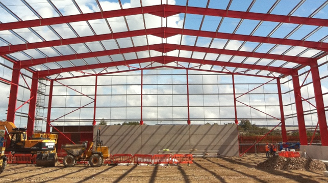
(Image courtesy of William Haley Engineering Ltd.)
- The purlins are adequately restrained by sheeting
- There is bracing of adequate stiffness in the plane of the rafters or alternatively the roof sheeting is capable of acting as a stressed skin diaphragm
- The rafters carry predominantly roof loads.
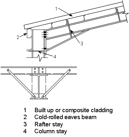
Ideally, the compression flange of the rafter or column should be laterally restrained by direct attachment of the purlins or cladding rails. However, under the action of wind uplift, or close to the haunches of a portal frame under gravity loading, the inner flange of the member, i.e. the one to which the cladding is not attached, will be in compression and cannot be restrained directly by the purlins or cladding rails. In this situation, the frame designer can either introduce an additional hot rolled steel member (often a structural hollow section) to laterally restrain the compression flange or, alternatively, the compression flange can be effectively held in position by a combination of lateral restraint to the tension flange (provided by the purlins or rails) and torsional restraint provided by rafter or column stays. Recommendations for the provision and design of restraints are given in EN 1993:1-1[18], Section 6.3.5.2 and Annex BB.3.
Rafter or column stays, as shown, may be used to provide torsional restraint to the rafter or column provided that they are connected to a suitably stiff purlin or cladding rail. Thin cold formed steel straps (working as ties) are often used, although angles may be used if the stay must work in compression (for example, if a stay can only be provided on one side of a member).
Restraint of purlins and cladding rails
Purlins and cladding rails are normally selected from manufacturer’s load/span tables, which are derived from analytical models supported by test data. In producing their design data, all purlin manufacturers have to make a judgement regarding the degree of restraint that is available from the cladding system under gravity and wind uplift conditions. These assumptions are central to the design model and can have a significant effect on the design resistance of the purlin or rail. It is therefore essential that an equal or greater level of restraint is achieved in practice. This will depend on the choice of sheeting and the spacing of the fasteners.
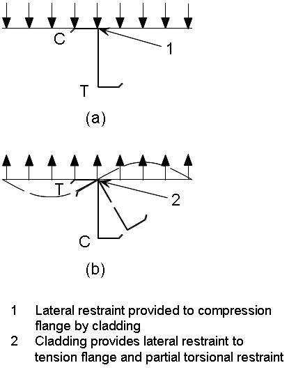
In the gravity load case (or positive wind pressure in the case of a wall), restraint is provided directly to the top flange of the purlin (or side rail) by the liner sheet or insulated panel, as shown. Built up cladding and insulated panels are generally capable of providing sufficient lateral restraint for the gravity loading case. In general, perforated liners are not considered to be restraining and the supporting purlins should, therefore, be designed as unrestrained members.
For wind uplift (or negative pressure on a wall), the cladding cannot provide lateral restraint directly to the compression flange. In this case, the purlin purlin (or cladding rail) is restrained by a combination of lateral restraint to the tension flange and torsional restraint, as shown. The ability of the cladding to provide restraint is dependent not only on its in plane shear stiffness (including the fasteners), but also its flexural stiffness. BS EN 1993-1-3[17] includes a method in Section 10 for assessing the degree of restraint provided by the cladding in this case. Unlike the gravity load case, the cladding only provides partial restraint to the purlin rail. Consequently, the purlin manufacturers’ technical literature should always give a lower capacity for purlins subjected to wind uplift loading (or suction on cladding rails).
BS EN 1993-1-3[17] covers the design of purlins, liner trays and sheeting in Section 10.
Hot rolled secondary steelwork
As an alternative to cold formed steel, purlins and cladding rails may also be made from hot rolled steel sections. At one time, this type of purlin was common in industrial buildings, often used in conjunction with steel roof trusses. The development of cold formed purlins (which are considerably lighter and cheaper) meant that the use of hot rolled purlins became unusual in the UK and Ireland. However, hot rolled purlins can be used, often with long spanning cladding solutions such as deck and membrane or composite panels, where they are particularly useful for providing an intermediate support to structural decking, where the decking by itself is incapable of spanning rafter to rafter.
Hot rolled purlins have a higher load carrying capacity than all but the largest cold formed purlins. This means that they are generally used at much greater spacings than their cold formed counterparts, typically 3m or more. This wide spacing makes them unsuitable for plastically designed portal frames, which commonly require restraint to the rafters at approximately 1.8m intervals. However, they are suitable for elastic frames and also for spans beyond the range of standard cold formed purlins (above 8m). Hot rolled purlins could of course be used at closer centres, but this would be uneconomic in most circumstances.
A considerable advantage of hot rolled purlins over their cold formed rivals is their resistance to lateral torsional bucking, especially where rectangular hollow sections are used. This property is essential if the cladding is unable to provide adequate restraint against lateral torsional bucking. By contrast, cold formed purlins are only able to span as far as they do (typically 6m to 8m) because of the continuous restraint provided by the cladding. Similarly, where the local building regulations forbid using the cladding to restrain the structure, hot rolled purlins are the only viable alternative to long spanning decks running rafter to rafter. Of course, apart from hollow sections, hot rolled purlins are not immune to lateral torsional bucking and must, therefore, be designed with this mode of failure in mind.
Unlike cold formed purlins, it is not common for the manufacturers to produce safe load tables for hot rolled beams. Their capacities must, therefore, be calculated by a structural engineer according to the recommendations of BS EN 1993-1-1[18], taking account of the cross section resistance, lateral torsional bucking and deflections. This process must be repeated for gravity and wind uplift load cases. If lateral torsional bucking is the critical design criterion, the resistance of the member could be enhanced by the introduction of tubular restraints either at the mid span or third points of the purlin. However, this will add cost to the structure in terms of additional steelwork and erection time.
Hot rolled purlins can be designed as single or double span beams. The latter option will significantly reduce the bending deflection of the purlin and should be used where deflection is the governing criterion. However, the high reaction at the intermediate support (1.25 x load in one span) can cause web crushing at this location. Sleeves are not generally used with hot rolled purlins.
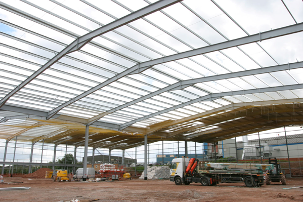
Other types of facades
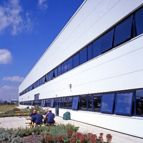
Many other types of façade materials may be used for industrial buildings, for example glass, as shown. The use of this architectural high-quality façade does not automatically lead to higher costs. In the example shown, hot-rolled sections are used for the structure as well as a standardised façade-system. By integrating solar gains into the thermal balance, running costs are also reduced significantly. The structure supporting the façade and the detailing can be adapted from solutions for multi-storey buildings, where these kinds of building envelopes are common practice.
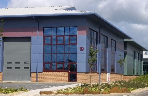
Another modern way of designing industrial buildings in an architecturally appealing way is of the use of different colours for the façade. A variety of colours, including pastel shading and metallic finishes, are available from many sheeting suppliers. The photograph shows an example of a building well integrated with its surroundings by the use of coloured facades. As an additional feature, photovoltaic panels may be integrated in the façade. Despite the fact that the angle to the sun is not optimal, the use of multi-layer coatings makes the solar cells less dependent on the angle of incidence of the sun’s rays. An example of this technology is shown.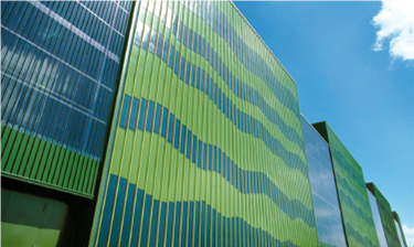
Façade with integrated solar panels
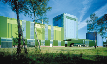
Industrial building with a coloured façade
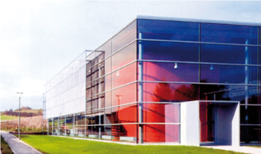
Industrial building with a glazed façade. Bauen mit Stahl e.V.
Procurement
Although there are many procurement routes in general construction, there are only two routes in common use in the industrial buildings sector: ‘Design and Build’ and ‘Traditional’. Of these, ‘Design and Build’ has by far the largest share of the market.
The prime attraction for the client of the Design and Build process is that the risks are passed to a contractor, who is responsible for all the design and construction aspects. The contractor’s role is to manage all of the activities and ensure the quality of the completed building. This situation works well, because there are sufficient companies within the steel construction sector who have the relevant competence and financial strength from which clients can select their team.
The selection of the supply team is critical to the success of a project. Clients should select an Architect and, where necessary, an Engineer who is familiar with their business needs and the type of work envisaged. The appointment of the Main Contractor and specialist sub-contractors should be discussed between the client and his advisors who are already in place. Help is available from reputable trade associations such as the Metal Cladding and Roofing Manufacturers Association (MCRMA) and the British Constructional Steelwork Association (BCSA). The latter maintains a Register of Steelwork Contractors with guidance on the type and size of contracts for which they have the skills and financial stability.
Building envelope installation
The functional performance of the building envelope is dependent on the correct specification of the individual components that make up the cladding system, the manufacturing quality of these components and the standard of installation. Good performance also requires a high degree of interaction between the components within each system and between systems (e.g. between the frame, the secondary steelwork and the cladding). This interaction requires the specification of components that complement one another and the ability and willingness of the specifier to take a ‘whole building’ approach to the design process. Good interaction also requires high standards of construction, especially where the connections between components are concerned.
Good practice guidance on the storage, handling and installation of the secondary steelwork, the wall and roof cladding and associated components can be obtained from SCI P346.
Good practice guidance on the installation of purlins and side rails is also available from the Metal Cladding and Roofing Manufacturers Association in Guidance document GD 24.
Resources
- SCI P313, Single storey steel framed buildings in fire boundary conditions
- SCI P346, Best Practice for the Specification and Installation of Metal Cladding and Secondary Steelwork
- SCI P380, Avoidance of thermal bridging in steel construction
- SCI P347, Single storey buildings
- Achieving airtightness with metal cladding systems. Steel Industry Guidance Notes SN06
- Thermal performance. Steel Industry Guidance Notes SN47
- Guidance document GD 24 – Installation of purlins and side rails, MCRMA, January 2016
Colorcoat® Technical Papers:
- The role of the building envelope in Part L 2010 compliance
- Acoustic performance of pre-finished steel cladding systems
- Creating an air-tight building envelope
- Ensuring consistent appearance of pre-finished steel wall cladding
- Fire performance of pre-finished steel cladding systems
- Structural performance of built-up roofing and cladding systems
- The effect of gauge on pre-finished steel roof and wall cladding performance
- Refurbishment solutions for non-domestic buildings