Steel is the most suitable material to use to support facades in circumstances where glazing has to be supported over distances of more than about four metres. The strength and stiffness of steel is such that supporting elements are of smaller section and therefore less obtrusive than would be the case with other commonly-used materials such as aluminium.
Tubular and tension elements are used in atrium roofs and vertical facades to form elegant and minimally intrusive support for glazing. Large deflections can be managed by careful detailing of fixings to glazing, such that local bending of the glass is avoided.
Atrium Roofs and Sky lights
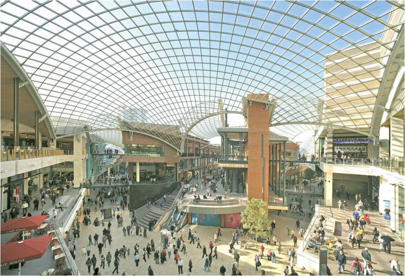
Atria are common features of office buildings where the layout involves large floor plates. In shopping centres, the external walls tend to have few windows and stores generally face onto an internal “street” which is extensively glazed at roof level. The roof glazing allows natural light to penetrate deep inside the building for the benefit of the users and to reduce the energy consumption of artificial lighting.
The structural systems used to support these roofs are designed to maximize the amount of light entering the building, using members of the minimum width possible. Tubular members are often used and painted in a light colour so as to absorb as little light as possible.
Glazing systems with pressure plates
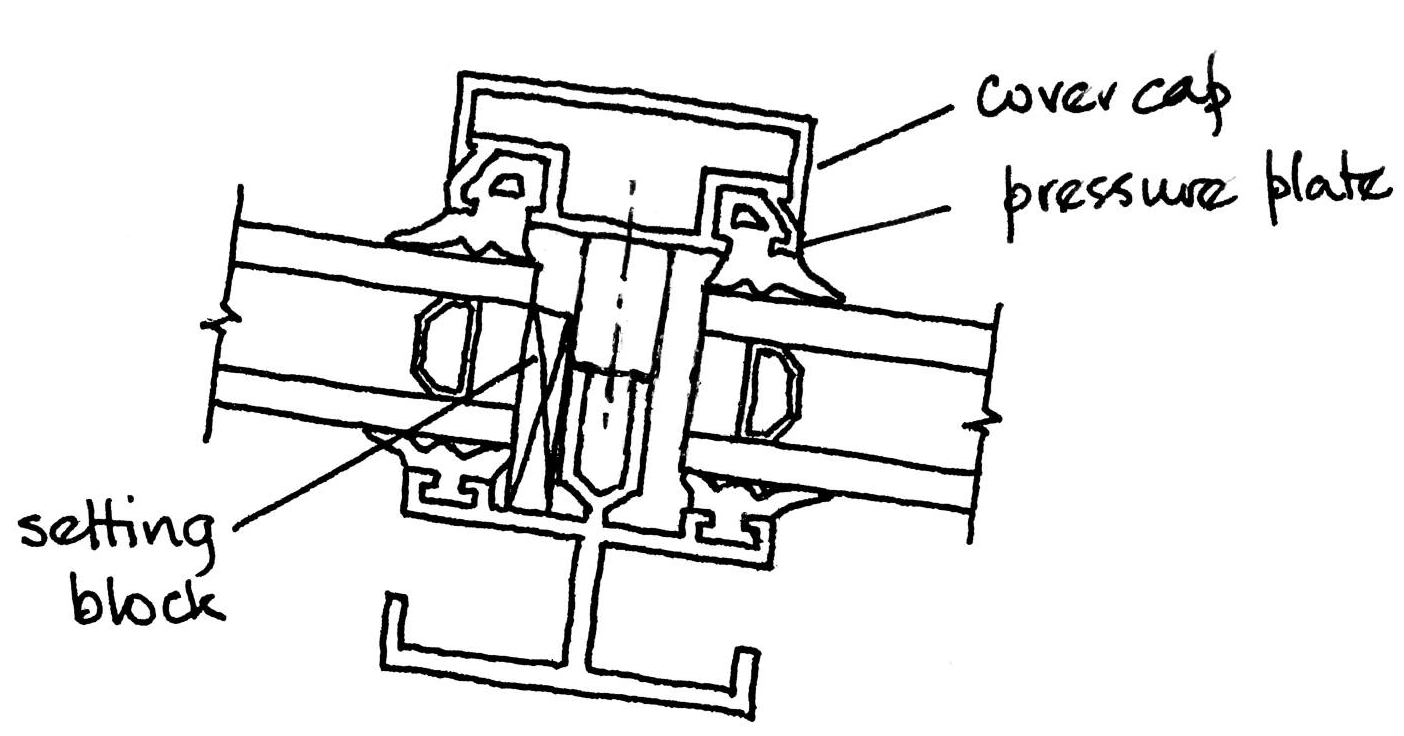
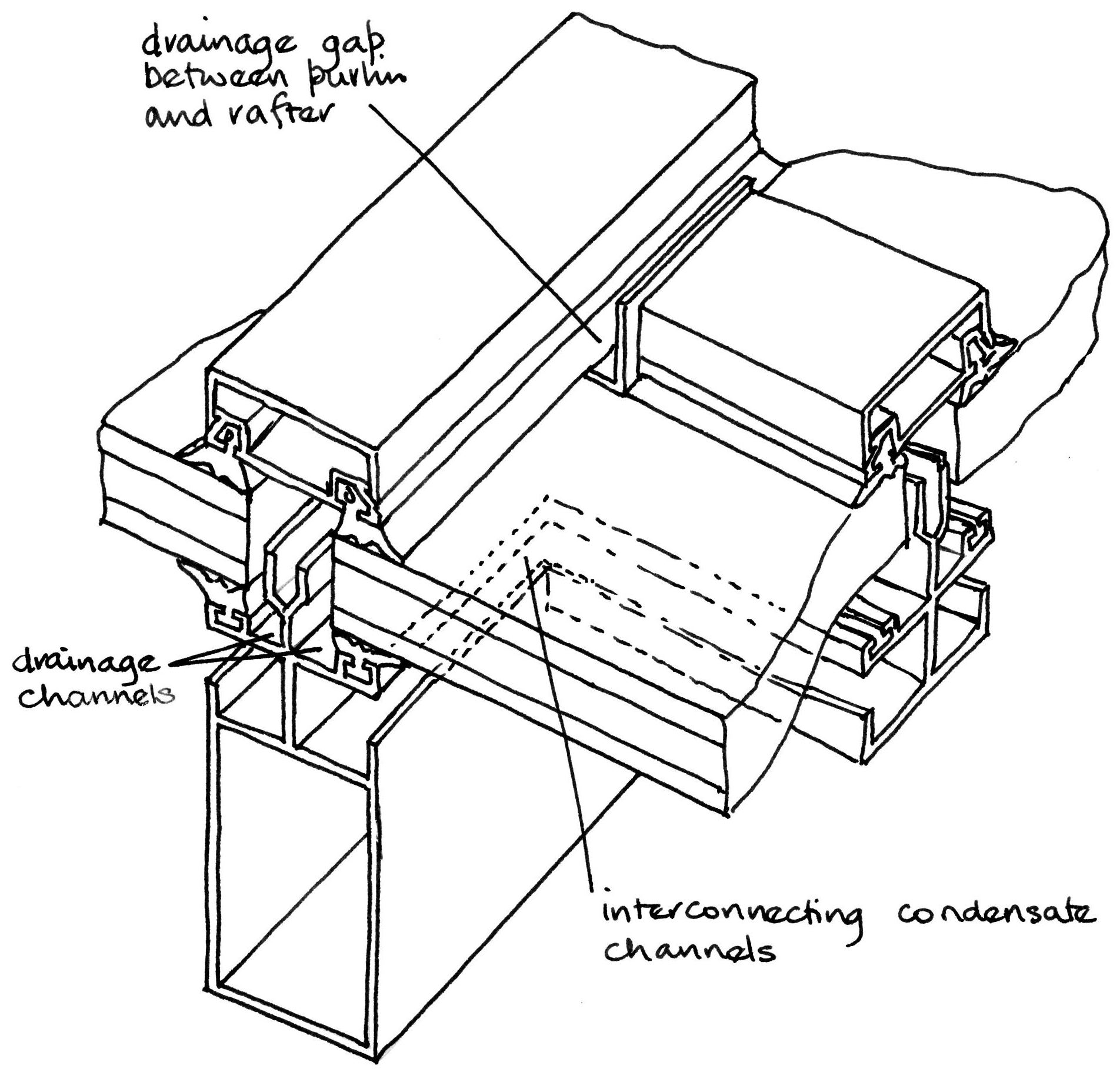
Water management is fundamental to the proper functioning of the sky light glazing system. The slope of the roof has to be sufficient to prevent the deflection of glazing and supporting members from causing ponding and to provide sufficient flow velocity to wash dirt away. Rainwater will inevitably be prevented from draining freely away by purlin pressure plates but gaps should be provided at the junctions between rafter and purlin pressure plates to allow most of the water to run off. Cover caps which clip onto the pressure plate provide an aesthetic external finish to the glazing bars.
Rafters and purlins are designed with drainage channels which interconnect as a secondary drainage path such that any water which passes the gaskets at the edge of a pane of glass is collected and conducted down the roof to discharge at the bottom of a rafter. A secondary potential source of water is condensation on the inside surface of the glass which the supporting elements are also designed to collect. Condensate drainage channels on the purlins discharge into similar channels on rafters and are drained to the exterior at the bottom of the roof. The elements for this type of roof are usually extruded in aluminium because the profiles required to accommodate pockets for gaskets and to form condensate drainage paths are easily extruded.
Steel rafters supporting aluminium profiles
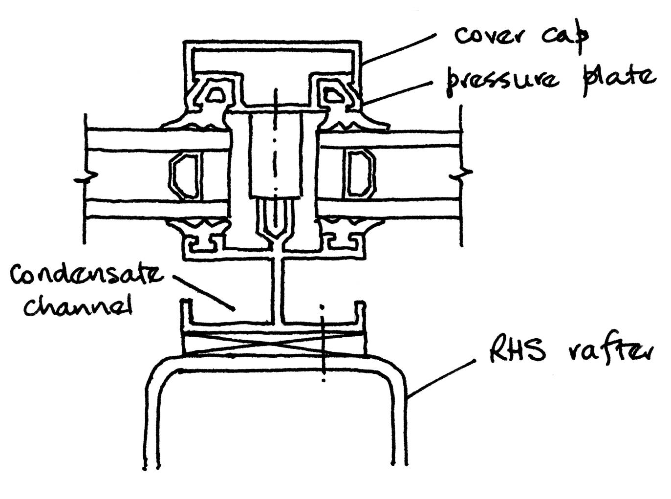
The connections between the structural steel rafters and the aluminium profiles must be provided with adequate adjustment so that the glazing can be installed to façade engineering tolerances which are often about +/- 2 mm.
Silicone-pointed glazing
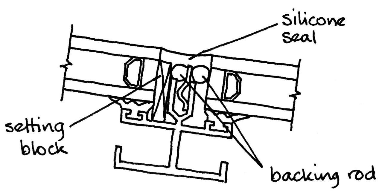
This type of glazing can be used for a shallower roof slope than purlins with pressure plates behind which water would be trapped leading to dirt build-up. The glazing spans one-way against uplift forces (rafter to rafter) but is supported on four sides against inward pressure.
Glazing can be retained using discrete fixings at intervals on the edges of the panes. These “patch fittings” are bolted through the joints between the glazing units into the supporting steelwork. They are isolated from the glass by a nylon-based plastic washer and bush and the joints are silicone pointed to provide a seal. A flush surface can be achieved interrupted only by the patch fittings which retain the glazing against uplift forces.
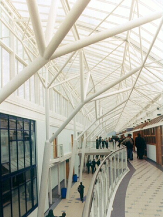
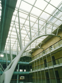
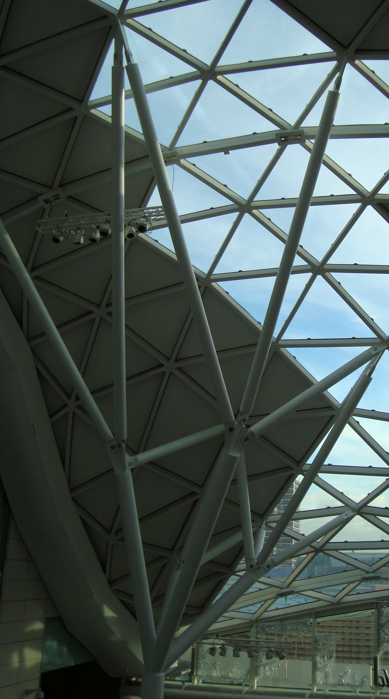
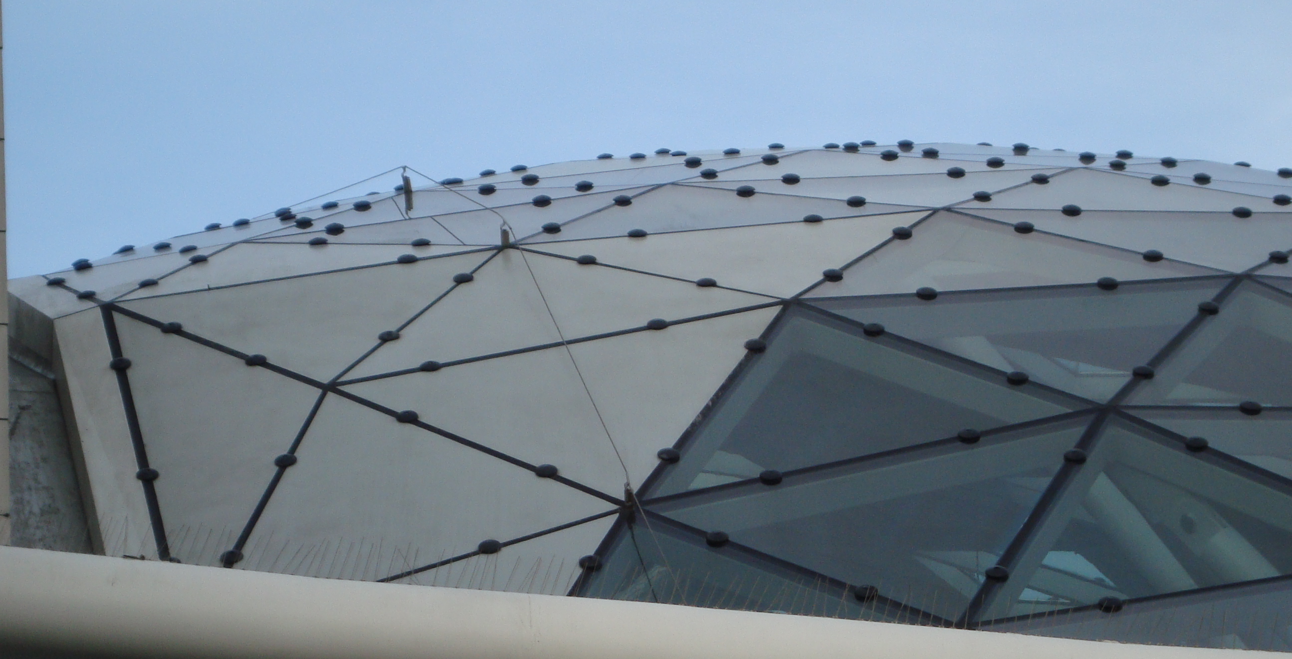
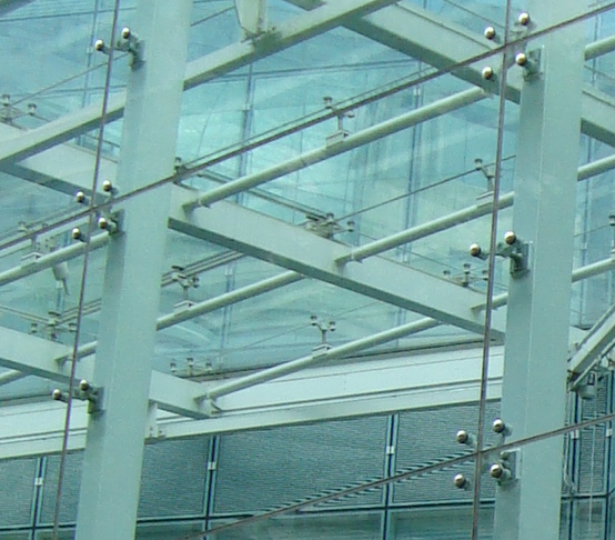
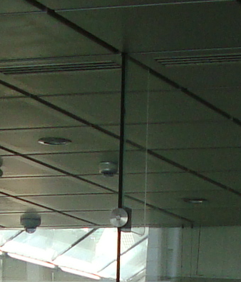
In the roof illustrated, triangular glazed units form a facetted surface following the supporting steelwork. In this arrangement of roof glazing the roof is face-sealed and has no secondary path for water in the event of failure of a silicone joint and no means of dealing with condensation as can be seen from an internal view of the roof below.
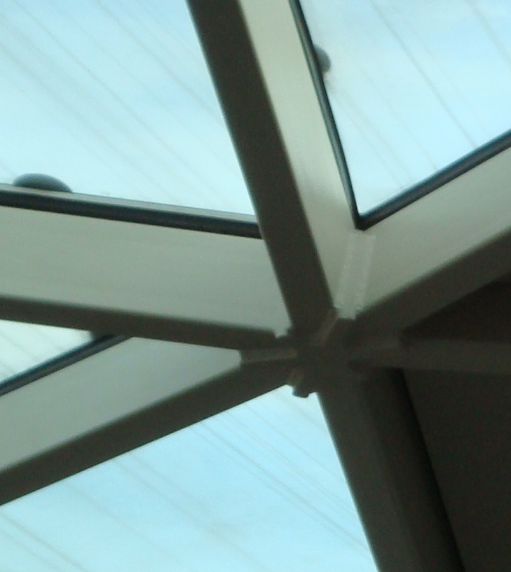
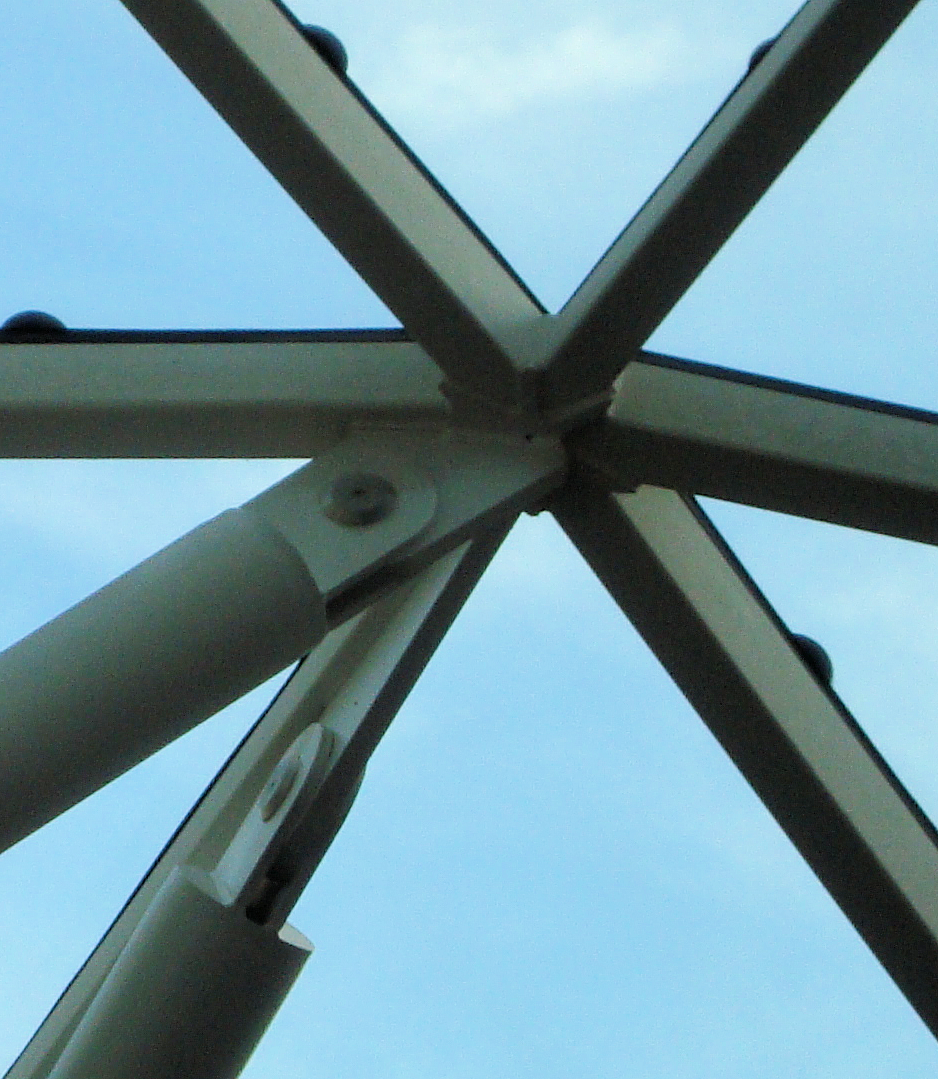
Joints between the steel grid shell elements are welded, making use of parting plates to assist with fabrication tolerances, as can be seen in the photograph. The grid shell is supported in this case by “trees” made from circular hollow sections. Pins are used to make simple and aesthetically pleasing connections between the grid shell and the supporting trees.
Vertical Facades with steel mullions
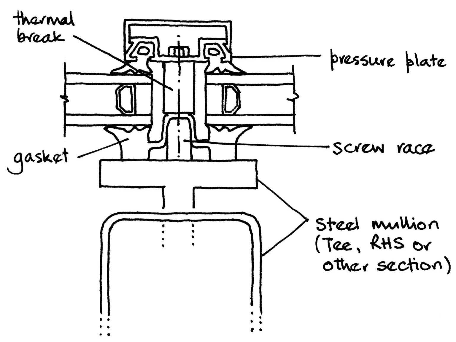
Gaskets fixed to the steel mullions provide the support to the inside surface of the glazing. A pressure plate bolted to the steel element is used to clamp the glazing in place.
Deflection is often a limiting criterion for the design of the supporting structure and the higher elastic modulus of steel compared with aluminium means that for long spans, the former is used by preference as the material for mullions. The mullion element can take a wide range of forms: tee and RHS sections are illustrated (left).
(Image courtesy of Arup)
Truss mullions with horizontal arms are used to provide lateral and vertical support to a glazed entrance. Bolted stainless steel fittings are used with eight bolts per pane in the illustration (below).
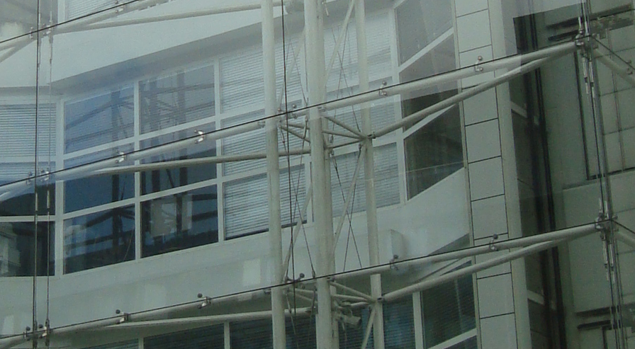
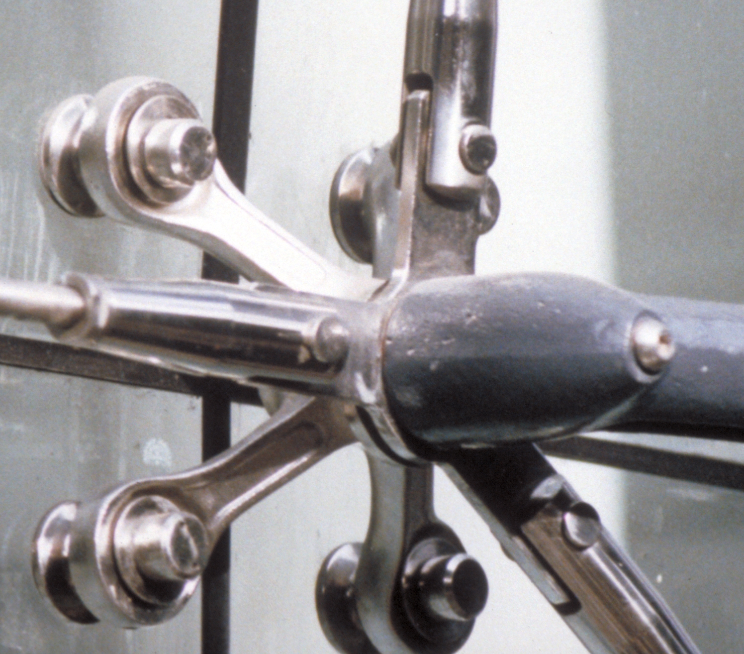
The Western Morning News building has tapered curved steel columns which support the roof structure and form the mullions for the outward sloping glazing. The glass is supported laterally by arms fixed to the columns and vertically by cables suspended from the tops of the columns. Stainless steel spiders provide the connection between the glass and the supporting elements.

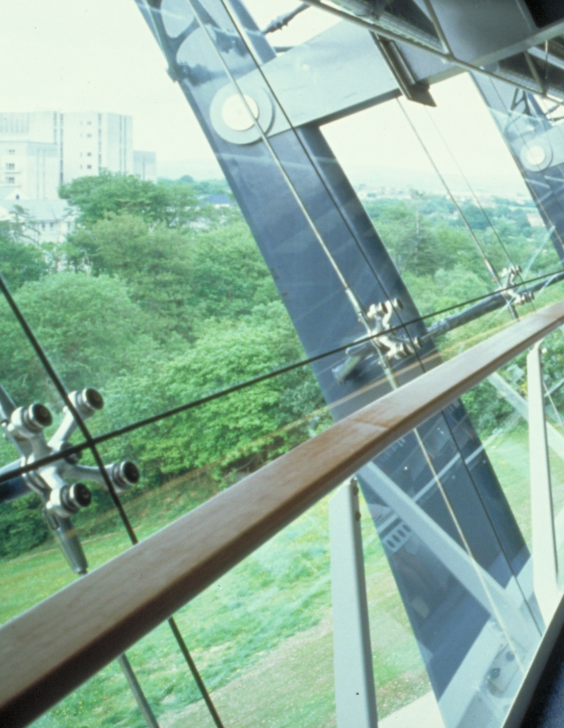
Cables are tensioned to maintain the stiffness of the element under reversal of loading. If this was not done, a load which put the cable into compression would result in a slack cable and a more flexible element for this load case.
(Image courtesy of Arup)
Point-fixed glazing
Point-fixed glazing was first used on Les Serres, Parc de La Villette. The glass panes used on this project are about 2m square and are suspended from a secondary steel frame.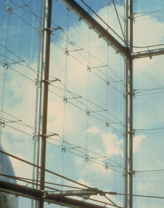
(Image courtesy of RFR)
A stiff rod connects back to the cable truss. Silicone pointing seals the joint between the glass panes.
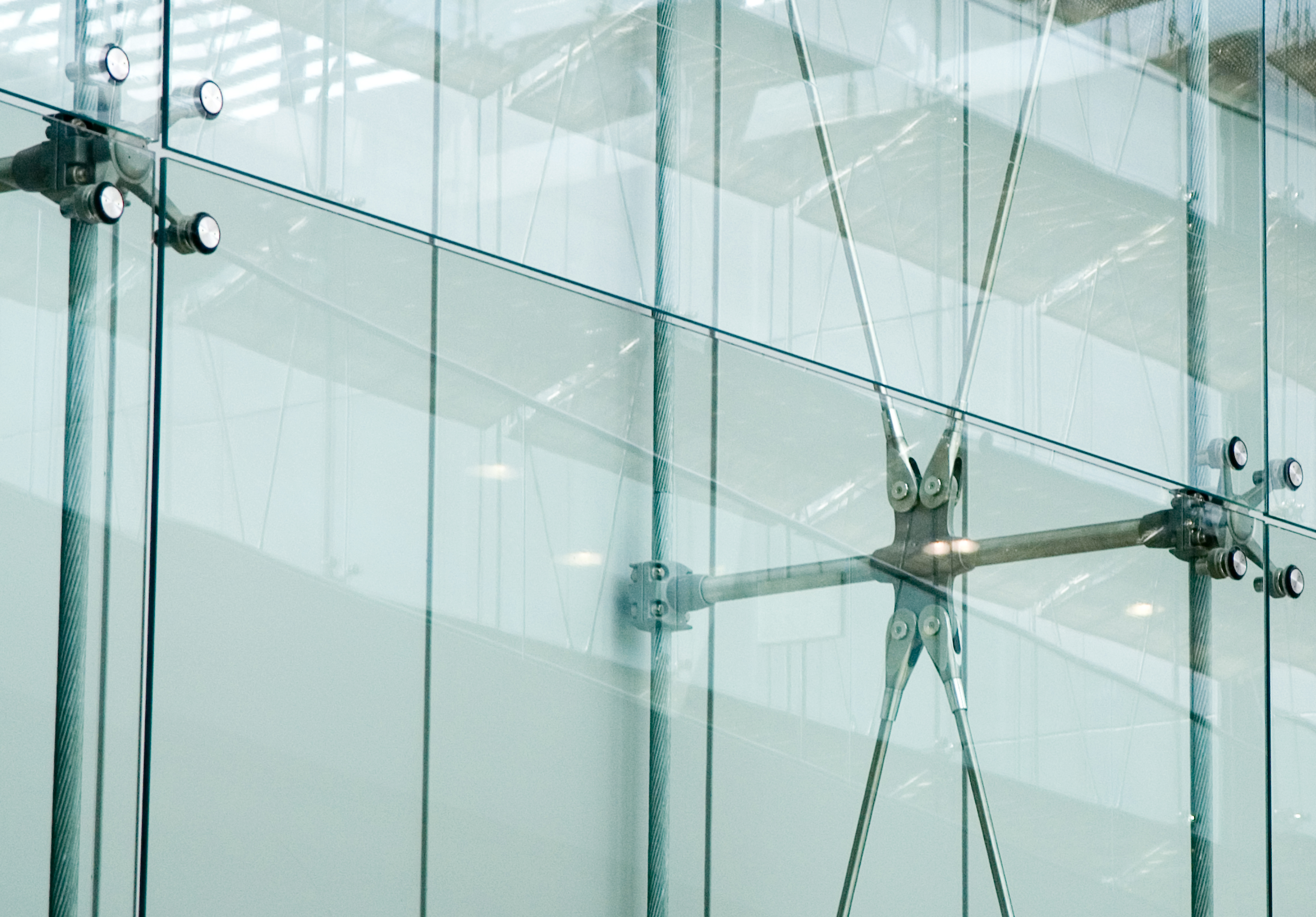
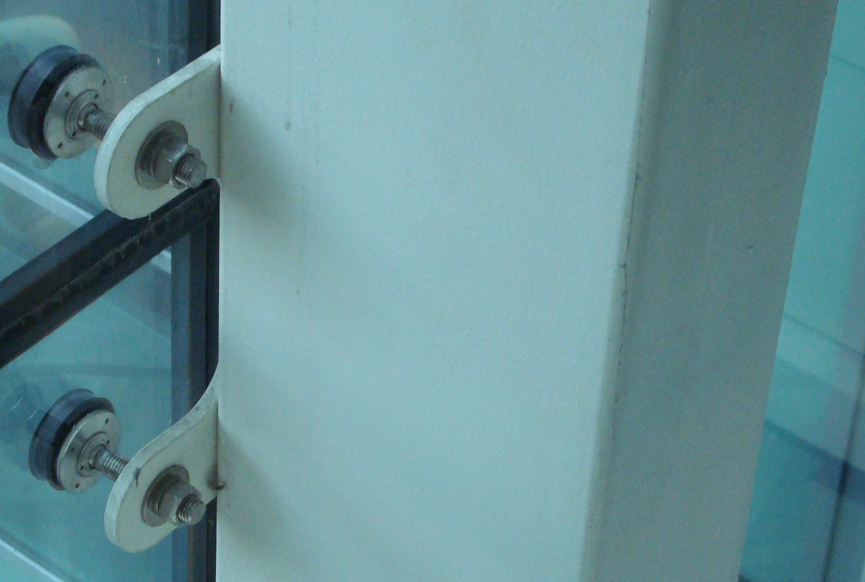
In the example below, glazing is supported from RHS mullions with point-fixings.
A stainless steel threaded rod provides out of plane adjustment and bending stresses in the glass are avoided by adopting a ball and socket joint as shown. Positional tolerance is taken up by using oversize holes in the glazing unit.
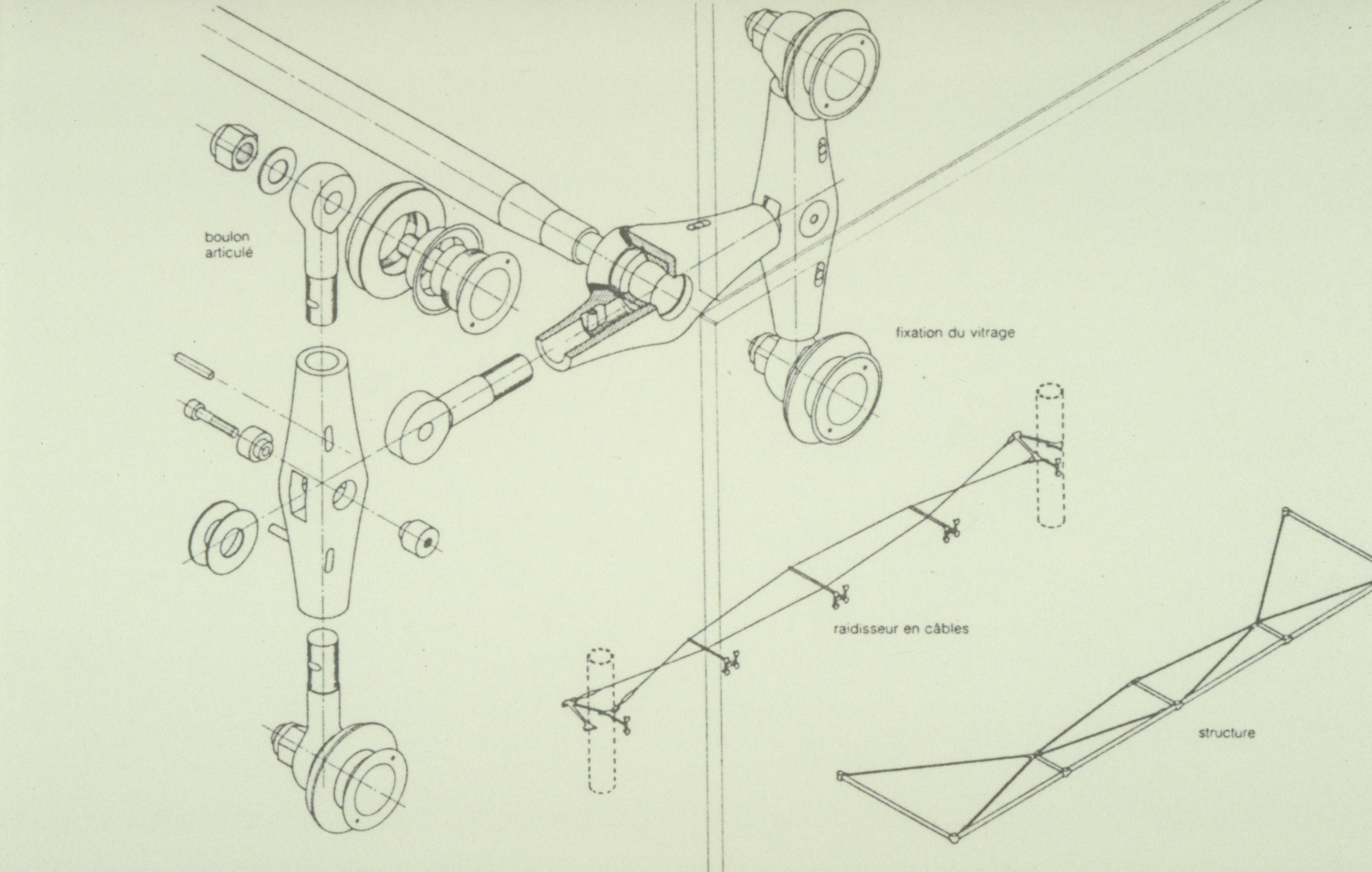
(Image courtesy of Arup)
Glass fins can be introduced instead of steel or aluminium mullions to increase the transparency of a glazed enclosure as shown below. The glass fins provide lateral support to the glazing in the same way as mullions do. Stainless steel point supports connect the façade glazing to the glass fins.
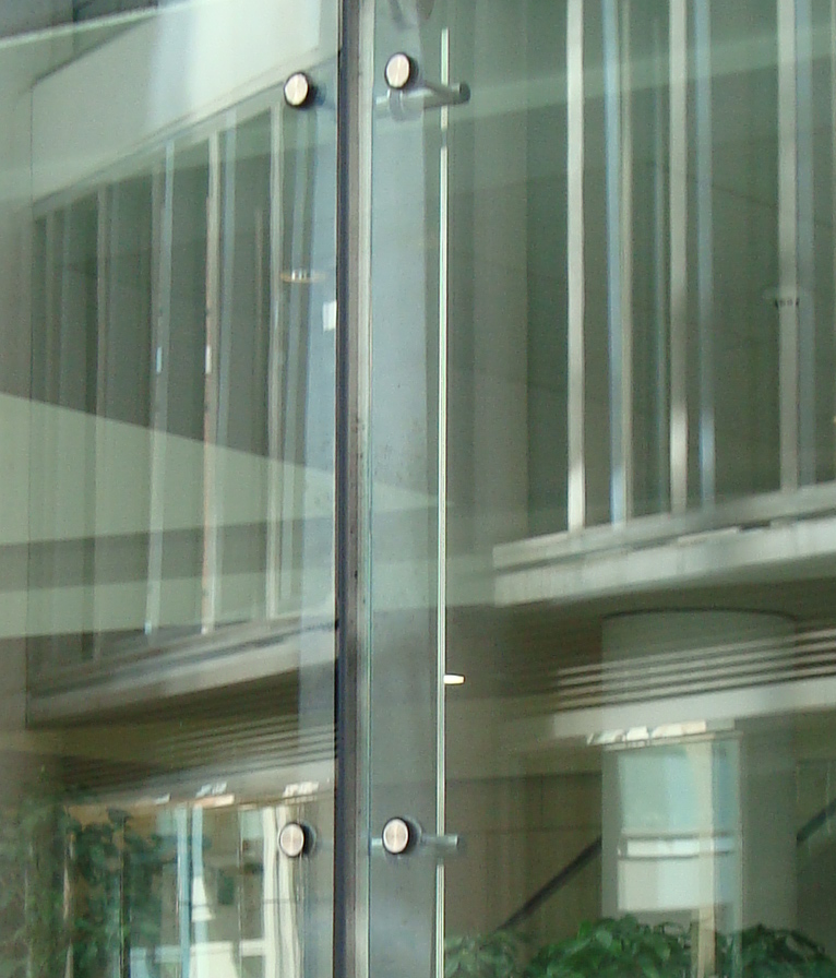
(Image courtesy of Arup)
This approach can be extended to the whole façade as illustrated. Stainless steel spiders are bolted to the fins using patch-fittings. A baked-on ceramic frit is applied to the glazing at floor levels. This provides a feature and hides the construction depth at floor level. It also provides shading to the interior.
(Image courtesy of Arup)
Cable supported facades
(Image courtesy of Tim Griffiths, Skidmore, Owings & Merrill LLP)
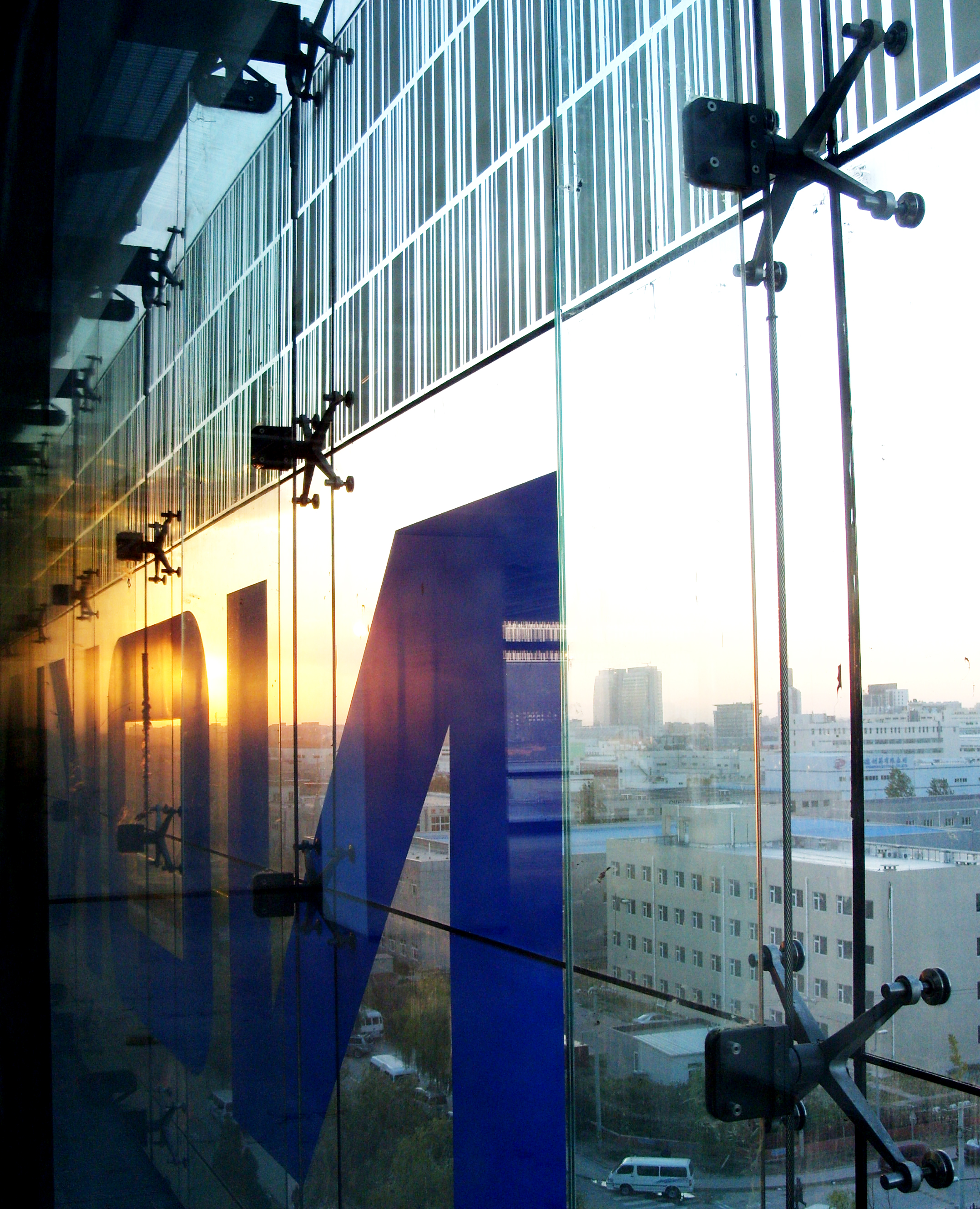
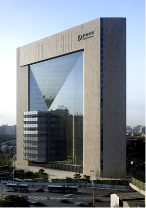
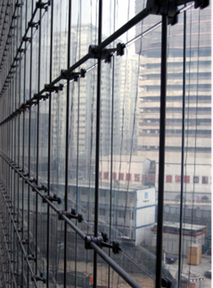
A more recent example is the Beijing Poly Plaza building where a glass wall 90m high by 60m wide designed by Skidmore Owings and Merrill is supported by an orthogonal cable net with stainless steel cables spaced at 1333 mm horizontally and 1375 mm vertically. Panes of glass of a slightly smaller size (to accommodate the joints) are clamped in place by stainless steel fittings attached to the cables at their intersection.
(Image courtesy of Skidmore, Owings & Merrill LLP)
(Image courtesy of Skidmore, Owings & Merrill LLP)
The cable net wall is divided into three sub-sections which are not coplanar as can be seen in the illustration, by large diameter pre-stressed stainless steel cables to which the orthogonal cable net is clamped. These large cables define the boundaries of the sub-sections and reduce the maximum deflection of the wall to 900mm. Further details of this cable net wall are presented in SCI publication P396.
The large deflections of the cable nets of the Beijing Poly Plaza and the Kempinski Hotel are achievable because the deformations of the glass panes and the seals at the joints between them are small. The loads causing the deformations are wind loads, applied over large areas of the façade. This means that abrupt angular changes in the cable net such as would result from point loading do not arise. The edges and particularly the corners of a cable net wall, where it abuts the rigid supporting structure, require careful detailing to make sure the deformations can occur without inducing unacceptable stresses in the glass.
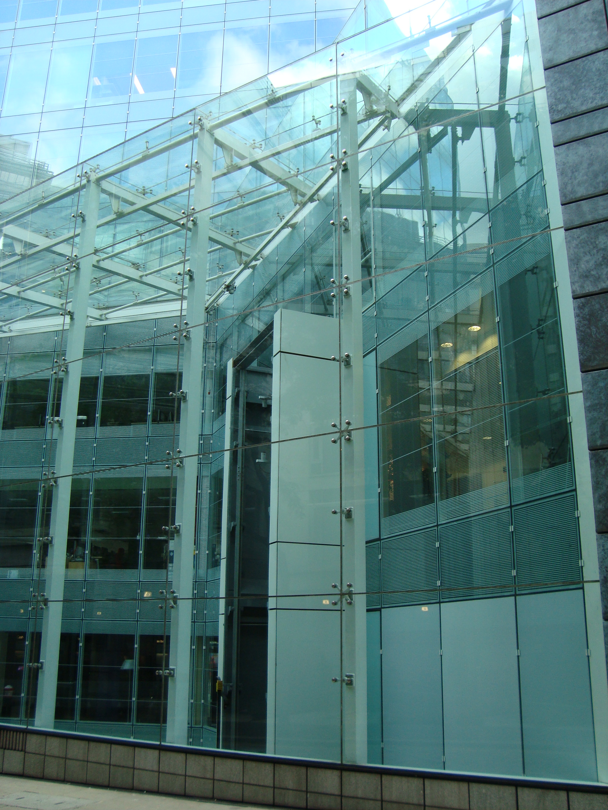
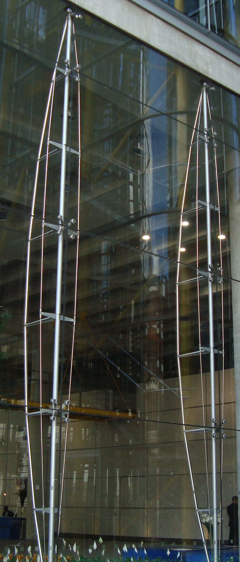
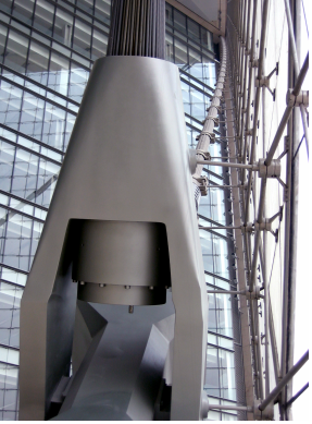
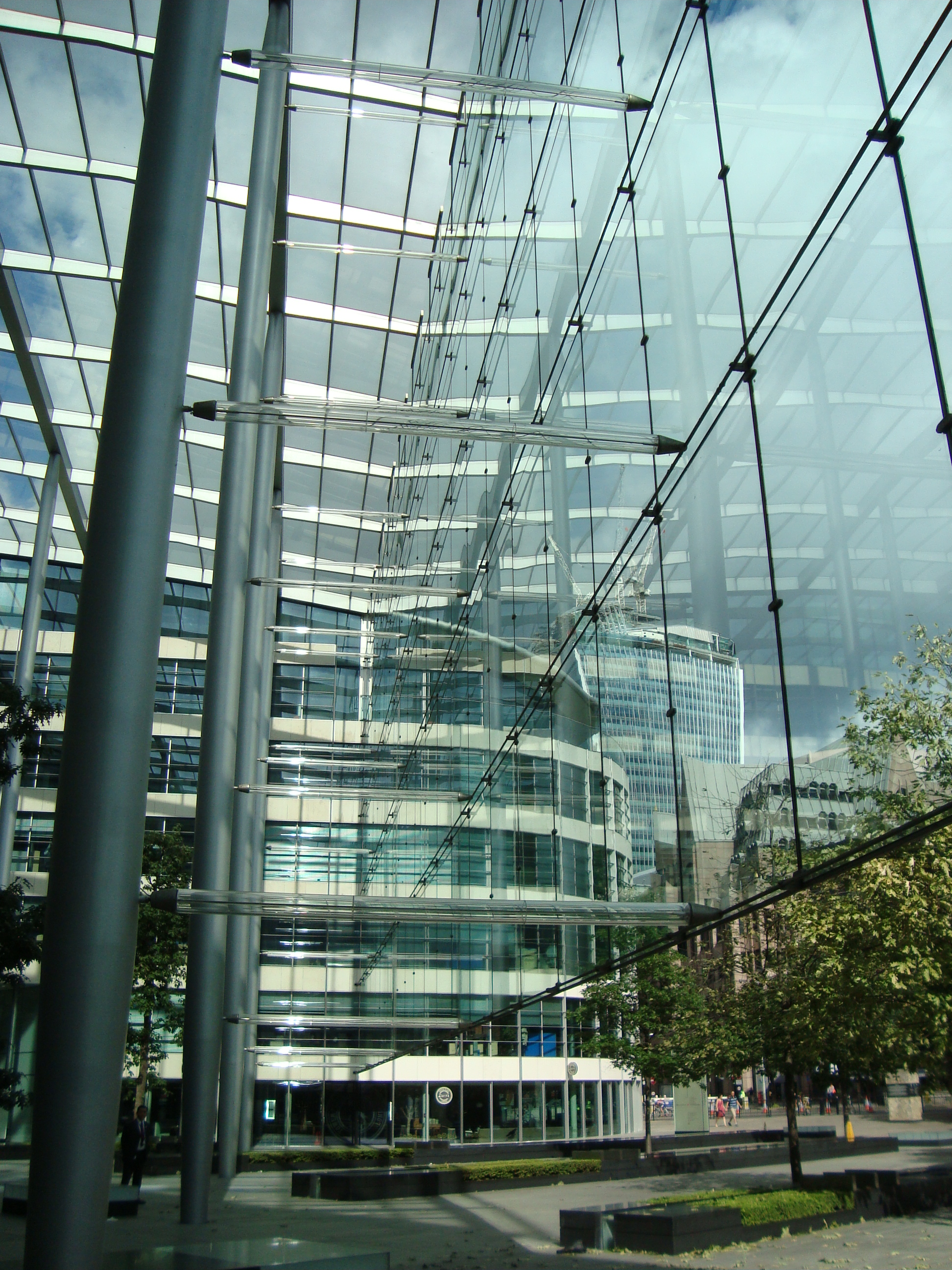
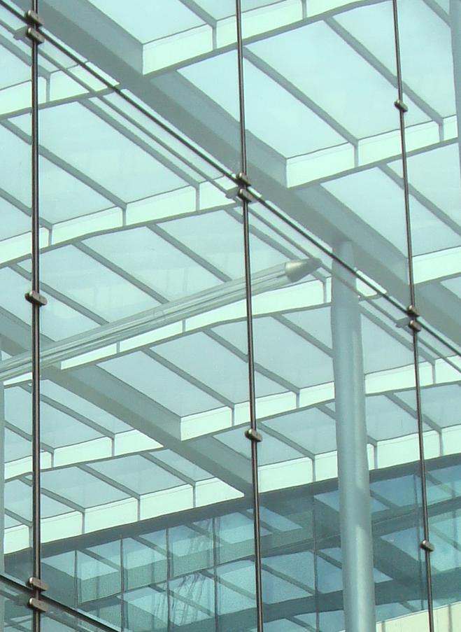
A further example of a cable-supported glass wall is the enclosure at Tower Place, London. A series of horizontal cables tensioned between the building structures at each end, provides lateral support to the glazed screen. The span of the horizontal cables is reduced by pre-stressed glass tubes, connected to the columns. The weight of the glass is carried to beams at the roof of the enclosure by vertical tension elements in the joints between the glass panes. Patch fittings are used to fix the glass to the tension elements.
The cables that form the cable net carry significant tensions and must be connected to structures that are sufficiently stiff and strong to resist these forces. The cable-net wall of the Beijing Poly Plaza is bounded by stiff reinforced concrete cores on the two vertical sides and by a three-storey high steel truss at the top. These substantial boundary elements are necessary to resist the tensions in the cables.
The glass wall at the Kempinski Hotel is reported as having a prestress in the horizontal cables of 85 kN each. Eleven cables span the full width of the wall so these apply a total lateral load of 935 kN (95 tonnes) to the supporting buildings.
It is clearly essential to choose this type of glazed wall early in a project so the appropriate strength and stiffness can be provided in the boundary structures.