The use of ‘integral bridge’ construction has grown to cover a large proportion of new-build highway bridge construction in the UK. Indeed, consideration of integral construction is required by highway authorities[1] for all bridges with an overall length up to 60m and no more than 30° skew. This article provides a general overview of integral construction for composite bridges. The effects of the soil pressures on the design of the bridge girders are also briefly reviewed.
Forms of integral bridge
There are four basic ways that a bridge can be made integral, depending on the abutment detail. The four forms of abutment can be referred to as:
- Frame abutments (fully integral bridges)
- Bank pad abutments
- Flexible support abutments
- Semi-integral end screen abutments
The forms of construction and some of the design issues are discussed below. For simplicity, the images show only the details at the abutments. The forms are equally appropriate to single span and to multiple span bridges; with multiple spans, the deck beams will be continuous over the intermediate supports.
Frame abutments (fully integral bridges)
For a retaining wall configuration, the supporting structure to a composite deck could be a relatively conventional reinforced concrete abutment (on either a piled or a spread footing), but such supports are stiff and could be subject to relatively large forces (due to the stiffness of the frame against horizontal expansion and contraction of the deck). An alternative for an embedded wall abutment would be the use of steel sheet piles, which offer an effective form of support and a more flexible frame, and thus minimises restraint forces and moments, but few examples of this form have been built.
Soil pressures behind frame abutments can be determined by limit equilibrium methods but soil-structure interaction needs to be considered for embedded wall abutments and thus there is an iterative procedure to determine soil pressures for design situations, although in practice the axial stiffness of the deck is usually so great that the displacements are not significantly modified by the interaction.
Bank pad abutments
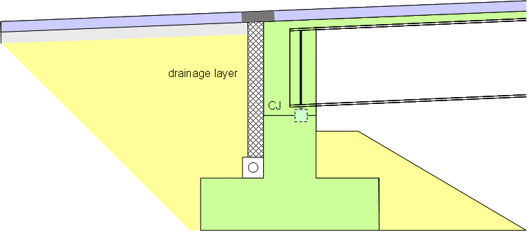
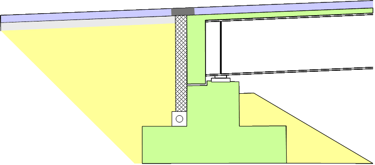
The abutment forms an ‘end screen’ wall that extends the full width of the road formation. Soil pressure on the end screen can be determined by limit equilibrium methods; soil-structure interaction only needs to be considered if the bank pad is supported on piles (and the piles are fully embedded in the soil). The allowance for movements between structure and pavement at road level are not significantly modified by any axial compressive strain in the deck. The image (above right) shows provisions for drainage behind the end screen wall and an asphaltic plug joint in the pavement. (Similar details are required behind the framed abutment configuration described earlier).
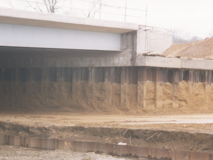
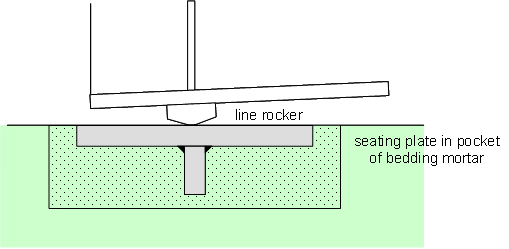
Whether a simple bank pad or a bank pad supported on piles is used, the lower part of the end screen wall is usually concreted first, leaving a horizontal construction joint. The main girders sit on this interface and are usually supported on ‘temporary bearings’. Typically, a pocket is left for the casting-in of a seating plate, which can be accurately levelled to suit the girders. Temporary restraint of the main girders, both laterally and longitudinally, needs to be provided, since the simple bearing detail does not provide restraint. The remainder of the end screen wall (around the main girders) is usually cast after the deck slab, to minimize the restraint moment due to permanent actions.
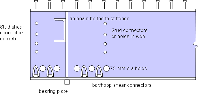
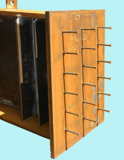
For the in-service condition, moment continuity from the main girders is achieved by the use of shear connectors on both flanges of the main girders, sometimes also on the webs of the girders, and sometimes by passing reinforcement through the webs. Hoops are often used because they have greater shear resistance. Shear connection on the underside of the bottom flange should be avoided, because it causes difficulties during construction.
(Image courtesy of Atkins)
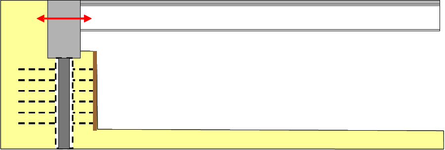
Flexible support abutments
Although the soil resistance to the longitudinal displacement of fully embedded piles (due to expansion and contraction) is modest, many designers have chosen to avoid this interaction, and the tendency to create ‘post holes’ around them piles by creating an annular space around them, between the underside of the end screen wall and original formation level (or the level of the roadway below). This is achieved by forming sleeves of precast concrete manhole rings around the piles or, for smaller piles, of polythene or UPVC piping. The buckling resistance of the pile over the length within the annulus then needs to be considered. To improve confidence about the durability of the columns within the annulus, some Technical Approval Authorities require provision for the annulus to be inspectable (by boroscope or similar instrument) – this can be achieved by providing a duct from the end screen wall.
Sleeves around piles
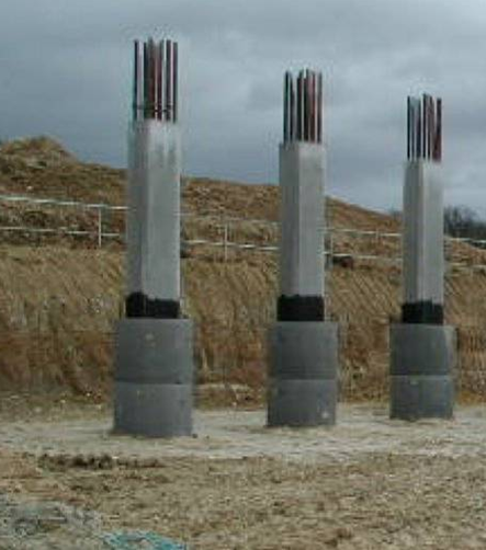
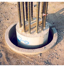
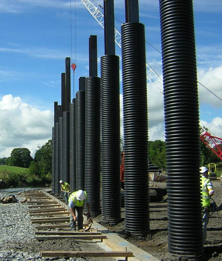
The sleeves should not be filled (or there is no benefit at all in providing them) and must be disconnected from the end screen wall at the top (or they will be dragged sideways by any movement); a movement interface must be created. Careful detailing is needed to ensure that the top of the annulus is sealed against soil ingress (a suitable detail is given in SCI P356). During construction, backfilling must be carried out in such a way as not to displace the sleeves and make contact with the pile.
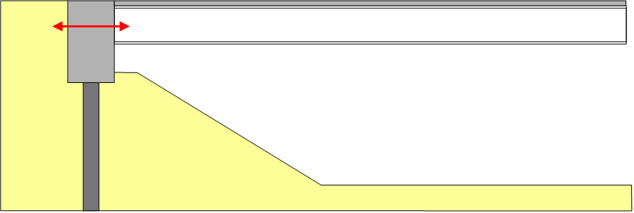
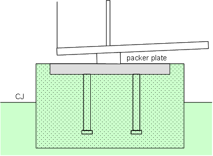
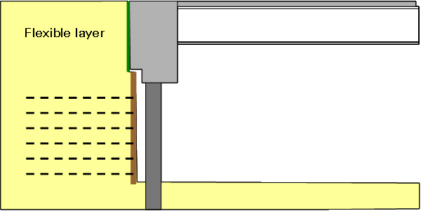
The diagrammatic arrangement of these sleeved, piled, bank pad abutments (termed flexible support abutments in PD 6694-1[2]) is shown in the two images below, the first for where there are conventional earth slopes in front of the abutment and the second for where reinforced earth is used with a vertical facing. Determination of effects due to expansion/contraction and flexure of the piles associated with bending of the beams can be modelled using a 3D frame model(see later discussion).
Where reinforced earth abutments are used, an alternative to surrounding the piles with fill is to locate them in front of the reinforced earth wall. This is a more buildable option, but may not always be acceptable visually.
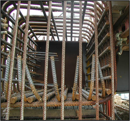
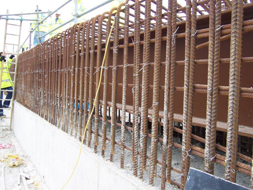
Moment continuity from reinforced concrete piles requires that the pile reinforcement extends well into the end screen wall. Continuity from steel H piles also requires significant length of embedment; shear connectors can be used to enhance the load transfer but are difficult to weld after driving. (An alternative that avoids welding in situ is the use of plunge columns, lengths of 'H' pile cast into the top of a bored/cast in place concrete pile).
The upper capping beam is usually quite heavily reinforced. Where there are tie beams between the main girders, care must be taken in detailing, to avoid congestion and to avoid creating difficult fixing details (for example, ties inside a cage of hooped bars). An alternative that avoids this conflict is to use bracing just in front of the end screen wall; if this is left in place it will need to be painted, otherwise removal is an additional site activity.
Concreting the upper part of the diaphragm wall after the deck slab will ensure that there is no moment transferred into the piles/columns due to concrete self weight.
Typical reinforcement details in end screen wall
Semi-integral end screen abutments
In this configuration there is an end screen wall that is integral with the deck beams, but the wall does not provide support to the beams. Support is provided from some other structural arrangement, and with bearings that accommodate horizontal displacement.
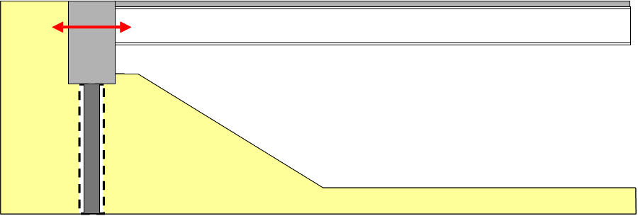
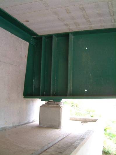
The image below shows a semi-integral abutment supported on a simple bank pad. A piled bank pad or a retaining wall type support could alternatively be provided. In either case, the supporting structure is not displaced or subjected to rotation by the movements of the deck beams: the usual soil bearing pressures can be mobilised and there is no need to design for flexure or temperature effects. BD 70/03[3] would permit this type of bank pad to sit on top of a reinforced earth retaining wall.
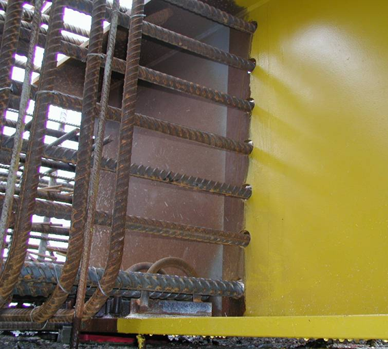
The connection between girders and the end screen wall can be achieved by the use of an end plate and shear connectors. The end screen wall will provide lateral and torsional restraint to the beams in service but some form of tie or bracing will still be required during construction. Examples of endplate connections are shown below.
Girder end details
Since conventional bearings are used, provision for bearing replacement must be considered. It is relatively straightforward to add stiffeners at jacking positions on the girders and to make space on the bearing shelf for jacks but the consequence on the retaining wall and pavement must also be considered. Vertical movement of about 5mm is needed to remove mechanical bearings and about 10mm for elastomeric bearings. A flexible layer between end screen wall and backfill should be provided to accommodate this movement and it must be recognised that the asphaltic plug joint will need to be renewed at the time the bearings are replaced. Nevertheless, the need to replace the bearings, with the consequent damage to the plug joint means that this is now a less favoured solution and may not be acceptable to some client authorities.
Intermediate supports
An integral bridge is necessarily continuous over intermediate supports (there are to be no provisions for movement joints at these locations) but does not need to be integral with the columns or piers beneath. The girders can simply sit on ordinary bearings. Eliminating the bearings by casting in the main girders or steel crosshead girders does not bring major benefits and does increase complexity in construction; the tendency to attract moment may also develop potential fatigue problems. The use of a reinforced concrete crosshead might be more amenable to achieving continuity with columns but substantial shear connection to the main girders is needed and temporary support of the main girders is needed while such a crosshead is being cast.
Dealing with skew
CD 350[1] says that integral construction should be considered for skews up to 30° and the design guidance given in PD 6694-1[2] is valid for skews up to this value. Recent experience shows that designers are designing fully integral bridges with skews up to or slightly above this value but semi-integral bridges are rarely designed with skews above about 20°. With semi-integral bridges there is less restraint from the soil to the lateral component of earth pressure on the end screen wall; restraint will have to be provided by guided bearings; they would need to be designed for these restraint forces.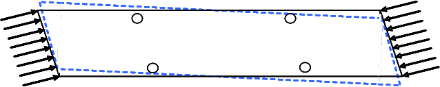
Pavement at the ends of the bridge
At the transition between the surfacing on the bridge deck and the pavement beyond the bridge, expansion/contraction is usually accommodated by an asphaltic plug joint. The maximum total movement range for such joints is stated in CD 357[4] as 40mm, which effectively limits the length of an integral bridge to around 80m.
The use of approach slabs would move the location of the plug joint away from the end screen wall (with potential benefit, should there be significant failure and leakage of the joint) but there are difficulties in designing satisfactory approach slabs and they are not currently favoured by many client authorities.
Additional support beneath a plug joint can be provided by a small mass concrete block above a blockwork drainage layer, as shown previously for the bank pad abutment.
Wing walls should either be entirely separate structures to the integral abutment, so allowing relative movement between abutment and wing wall, or, if there is little skew, can be joined to the end screen wall, provided that they are aligned to be a continuation of the bridge deck parapet line (i.e. in the direction of bridge deck movement) and kept as small as practicable.
Designing to the Eurocodes
Soil pressures
For design to the Eurocodes, BS EN 1997-1[5] does not provide detailed rules for the evaluation of forces due to soil pressures in integral bridges but this deficiency has been remedied in the UK by the publication of non-contradictory complementary information (NCCI) in the form of PD 6694-1[2].
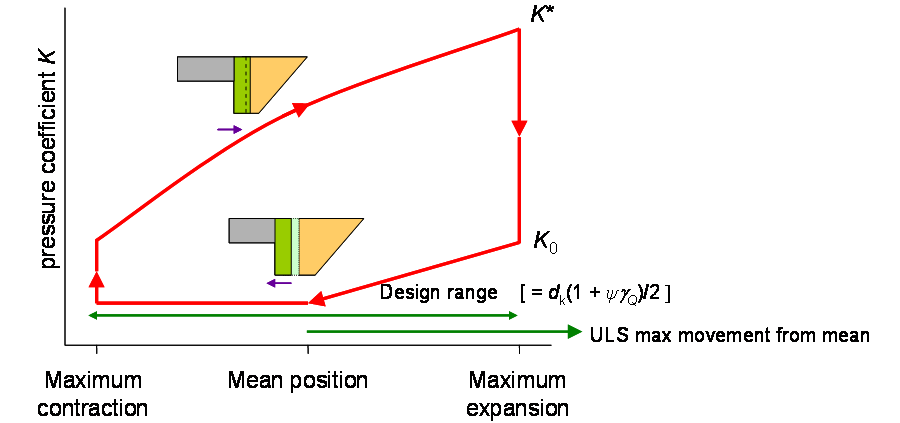
For determining the soil pressure behind the abutment wall, research has shown that after many cycles of thermal expansion and contraction, integral bridges follow a cycle of earth pressures that range up to a maximum value dependent on the 50-year return period characteristic value of displacement due to thermal expansion. The cycle is illustrated graphically below: daily variations cycle clockwise within the limits of the envelope. For unfavourable effects it should be assumed that the relationship is that for the upper line of the envelope.
Modelling structural continuity in global analysis
Frame abutments
Framed abutments need to be modelled with full moment continuity at the connection between the deck and the supporting structure. The endscreen walls are subject to soil pressure from the retained fill and the pressures are related to displacements, as noted above. If the columns are in contact with the soil, they too will be subject to earth pressure related to displacements, although the forces involved should be relatively small.
Sleeved pile abutments
The deck can be modelled as a conventional grillage, but it is essential to represent the physical depth and stiffness of the end diaphragm in order to obtain realistic pile head displacements/rotations. This is because as well as the horizontal movements induced by shrinkage and thermal expansion/ contraction, the pile head will also kicked out with rotation of the end diaphragm. Pile bending moments are induced by the horizontal displacement and rotation of the pile head at the underside of the diaphragm, so it is essential that the global analysis model captures this behaviour as realistically as possible. In the global model the piles can be modelled either with lateral springs along their length or as an ‘equivalent cantilever’, of length and stiffness determined from a soil structure interaction analysis using an appropriate pile analysis program. Where piles are inside rings or pipes, there is no need to model the soil resistance over that length.
Effects of soil pressure on girder design
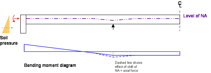
The soil pressure behind the abutment varies linearly with depth, so the centre of pressure on an end screen wall is at approximately 2/3 the distance from the top of the slab to the underside on the wall. For a semi-integral bridge or a fully integral bridge on relatively flexible piles, the centre of pressure is thus below the centroid of the girder cross section and induces hogging moments as well as axial forces. With continuous spans, the moment due to the pressure is thus sagging at the first support from the abutment and an additional sagging moment is introduced when the centroid of the cracked section is lower than that of the uncracked section at the abutment.
See also
- Multi-girder composite bridges
- Ladder deck composite bridges
- Bridges - initial design
- Modelling and analysis of beam bridges
- Design of beams in composite bridges
- Shear connection in composite bridge beams
- Fatigue design of bridges
- Bracing systems
- Stiffeners
- Connections in bridges
- Bridge articulation and bearing specification
- Skew bridges
- Design for steel bridge construction