A ‘half-through’ bridge configuration provides a solution for small and medium span bridges where the depth available between the trafficked surface (top of rails for a railway bridge) and the clearance level beneath the bridge is too shallow to accommodate the structural elements spanning across the bridge supports. This form of construction is more commonly seen in railway bridges and footbridges, but is sometimes used for highway bridges. This article provides an overview of this form of construction.
Definition of ‘half-through’
A bridge provides a running surface for the traffic that crosses it and to ensure minimum interface issues it is best to arrange all the structural elements below that surface – i.e. the traffic runs on top of the bridge structure. But the depth of structure (including the thickness of surfacing or ballast) that is needed may in some cases be too great to be accommodated between the level of the trafficked surface (as dictated by levels adjacent to the bridge and by maximum gradients) and the level of minimum clearance above the ground, river, road or railway below.
In such cases, a different structural arrangement can be adopted, in which the traffic runs through the structural envelope. There then are two basic options – a ‘through’ configuration and a ‘half-through’ configuration.
In a ‘through bridge’ the traffic is completely inside the structural envelope – typically the traffic runs inside a truss, with the trusses either side of the carriageway, top bracing above the carriageway and the deck that directly supports the traffic below.
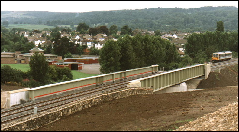
In a half-through bridge, the traffic is only partially inside the structural envelope – there are girders (or trusses) either side and a deck below but the girders are not as high as the traffic envelope and thus there cannot be any bracing to the top flanges (or chords). This means that a half-through bridge is in the form of a ‘trough’, i.e. it has a square U-shaped form.
This article illustrates the forms of half-through bridges. The design issues associated with the use of a half-through construction are discussed separately.
Forms of half-through bridge
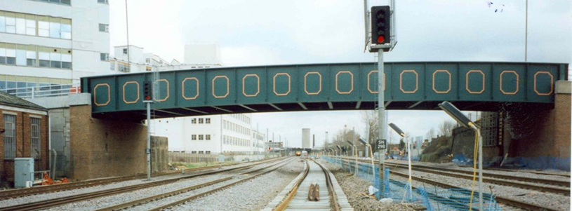
A typical cross sectional layout of a half-through plate girder railway bridge is shown below.
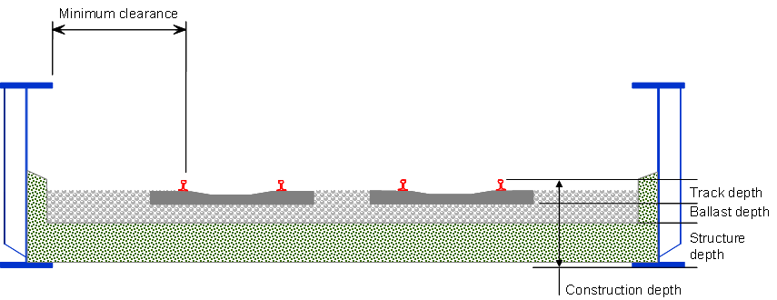
With the half-through form, lateral clearance has to be provided between the railway and the plate girders on either side. The clearance is needed both for the ‘swept envelope’ of the railway traffic and for access ways beside the track. Alternative arrangements for access ways outside the girders can sometimes be used, which reduces the clearance needed inside the girders, and where the girders extend upward only a small distance above the rail level, the distance from the track can sometimes be reduced further. Guidance on these alternative arrangements is given in SCI P318, which also lists the relevant railway standards.
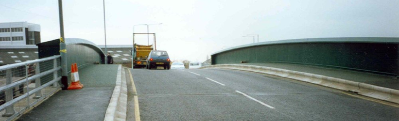
A typical layout for a half-through highway bridge is shown below.
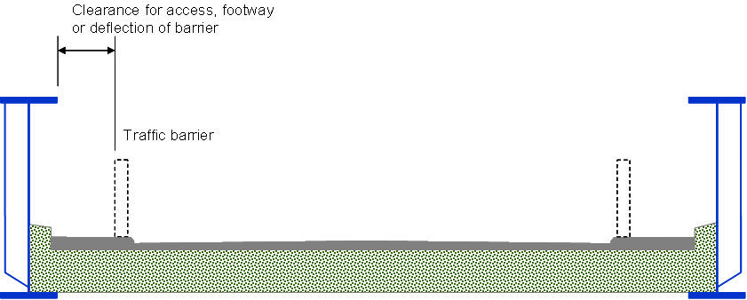
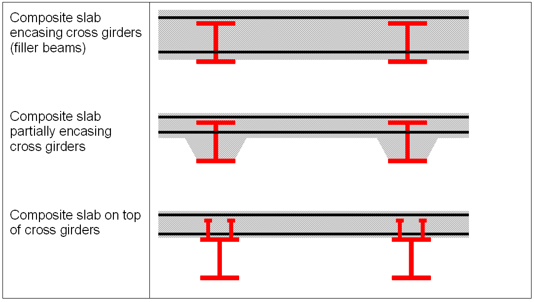
Deck construction
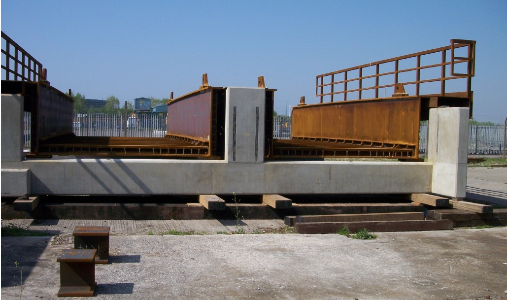
To achieve minimum structural depth, a composite beam and slab arrangement is usually adopted for the deck in railway and highway bridges. Three alternative beam and slab arrangements are shown below. In each case, the cross girders are connected to the main girders with end plate connection details.

U-frame configuration
Whether the deck is composite or steel, the configuration of the whole bridge, main girders and cross girders is usually similar to that shown right.
In the Figure it may be noted that, although the bridge is skew, the cross girders span square to the main girders and alternate cross girders align with vertical web stiffeners, forming a rectangular U-frame. It is this frame that provides the lateral restraint to the top (compression) flange and the design of the U-frame is fundamental to the performance of the bridge.
The use of doubler plates to provide sufficient flange areas, as shown, is common on railway bridges.

Half-through footbridges
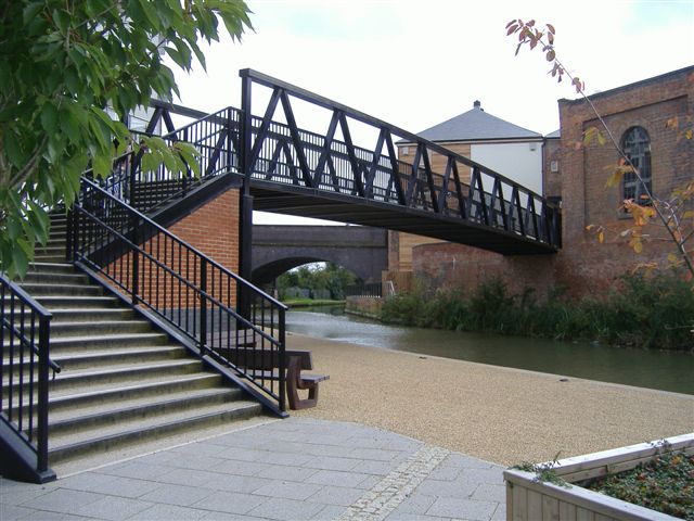
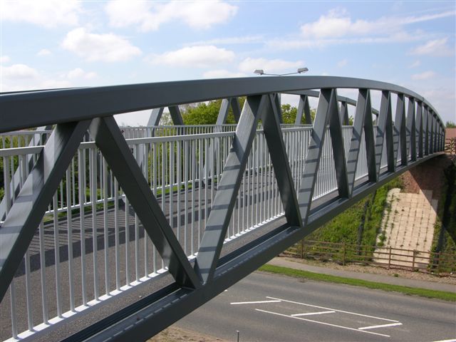
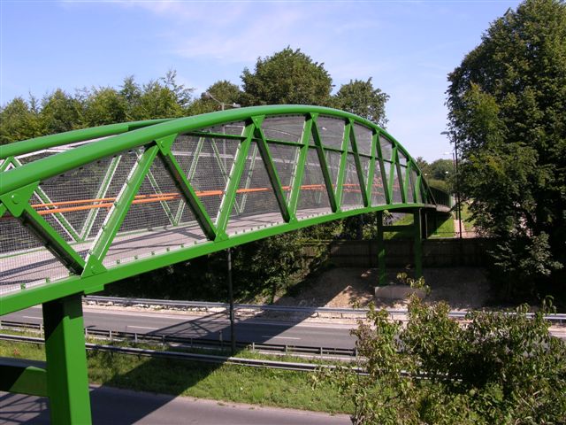
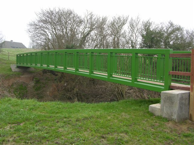
Half-through steel bridges are a common solution for pedestrian and cycleway bridges. The footway/cycleway is relatively narrow and a stiffened steel plate deck can easily span between open web main girders on either side.
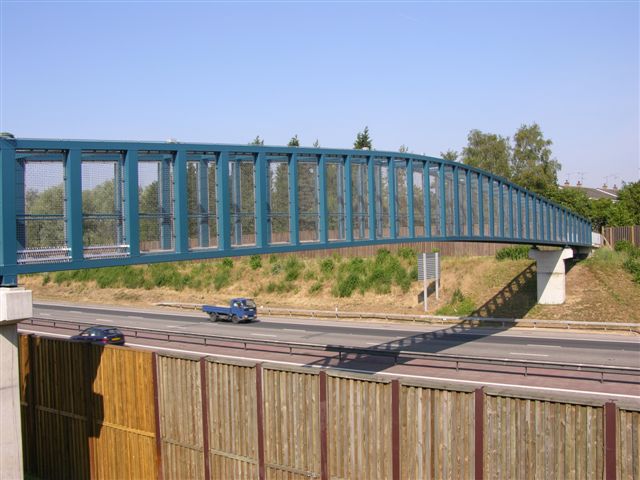
There are two options for the open web girders – a triangulated truss (usually Warren type) and a Vierendeel girder. In the latter case, the parapet is often incorporated into the girders , with handrails within each panel. In both cases, the deck is usually a thin steel plate with transverse and longitudinal stiffeners.
Warren truss half-through footbridges
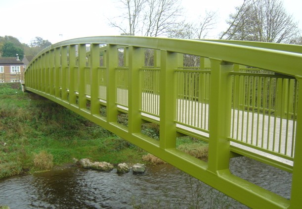
See Design of steel footbridges for more information.
Resources
- Iles, D.C. (2004) Design guide for steel railway bridges (P318) SCI
- Steel Bridges: A practical approach to design for efficient fabrication and construction. (51/10). BCSA
- Hendy, C.R.; Iles, D.C. (2015) Steel Bridge Group: Guidance Notes on best practice in steel bridge construction (6th Issue). (P185). SCI