Heron Quays Pavilion, Canary Wharf, London
On the water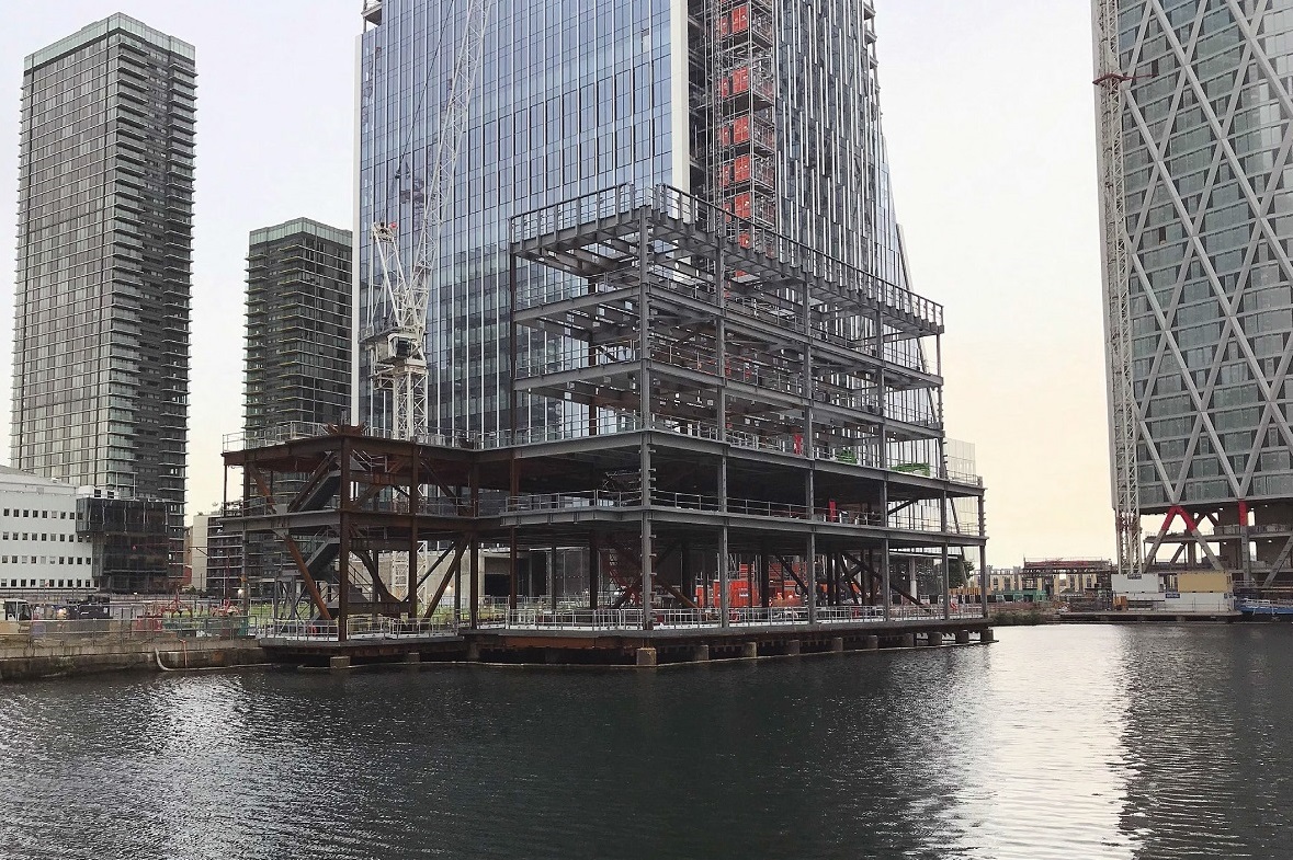
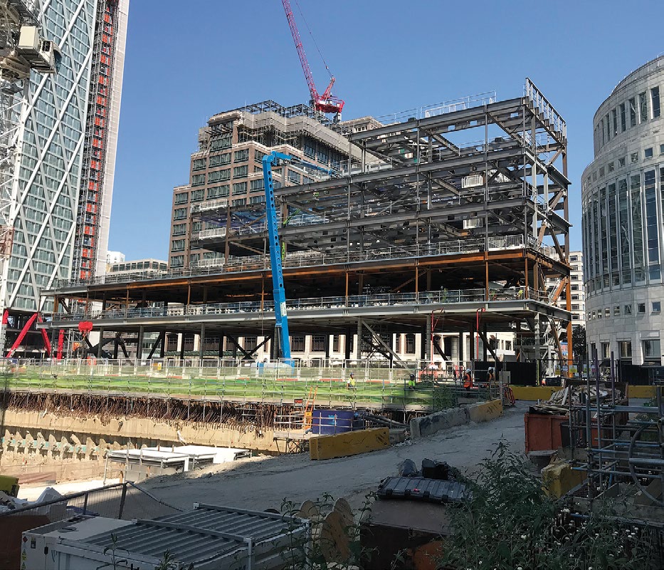
Sat on weathering steel grillage, spanning over a portion of Middle Dock in London’s Canary Wharf estate, a unique structure is under construction. Measuring 63m-wide × 23m-deep, the five-storey steel-framed structure will accommodate exclusive guest rooms, restaurants and leisure space, such as a gym and roof terrace for its members.
Numerous high-profile projects have been completed at Canary Wharf over the last three decades, including One Canada Square, which at 236m-tall was the UK’s tallest building until the Shard came along. However, this job is unique and main contractor Canary Wharf Contractors (CWC) has never attempted any similar projects as Senior Project Manager Eamon McDermott explains: “Whilst we have carried out many successful projects, including the Elizabeth Line station at Canary Wharf in close proximity to water, we have never constructed a building directly over a dock sitting on existing marine piles.”
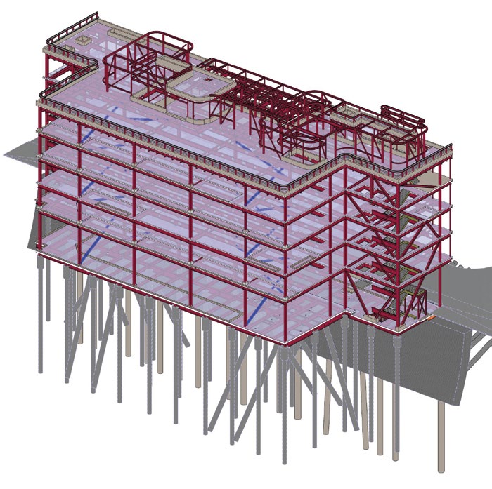
The project is utilising a series of existing marine piles and pile caps, which were constructed in the early 1980s to support low-rise office buildings and a logistics dockside deck that were demolished in 2017. They consist of 44 × 800mm diameter piles, all of which are encased in steel. “In order to re-use the existing marine piles, we had to survey and measure the corrosion rate of the steel casings to establish if the pile had sufficient bearing capacity,” adds Mr McDermott. The piles were originally designed for a minimum 100-year design life and, through various testing, CWC was able to confirm that they are still suitable for the projected life of the new structure.
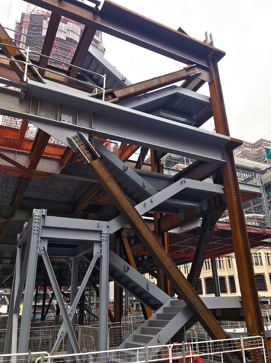
The initial steelwork installation consisted of erecting the steel deck, which forms the lowest level of the structure. This is made up of plated weathering steel beams, which have been designed to spread the vertical loading as evenly as possible to the piles in order to maximise the occupancy space within the building. This was achieved by using deep transfer beams under column locations to spread load from central columns to four piles and edge columns to two piles.
“We chose weathering steel for the deck because of its corrosion protection properties, and the fact that we are building the project in a marine environment,” adds Mr McDermott. “Initially, we looked at using corrosion protection paint, however restricted access between the ground floor and the water for inspections and maintenance made us re-consider. Also, concrete beams and pre-cast slabs were considered but again, due to weight restrictions, we decided to go with steel.”
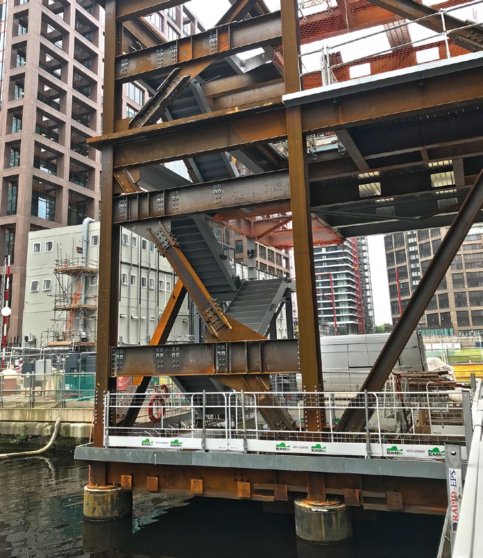
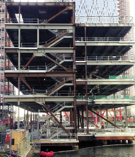
Sat on the weathering steel deck, the Heron Quays Pavilion is a five-storey braced structure. Stability is provided by steel bracing in the corners of the building as this ensures maximum useable space and flexibility for the client. The geometry of the bracing has been set out to avoid balconies and windows. This arrangement has meant that the bracing members need to take both tension and compression and have long lengths for buckling. As a result, the members are stiff and attract vertical loading.
In order to reduce the amount of vertical loading that the bracing members attract a temporary bracing strategy was put in place. This strategy involved temporary bracing placed in the central portion of the building during construction, which meant that the self-weight of the concrete slabs was pushed into central columns and locked in place by the time that the permanent bracing structure was in place. This reduced the loads on both the bracing system itself and on the most critical piles. The bracing system was also stiffened using welded plates to reduce the sway deflections of the building.
Steelwork is based around an irregular grid pattern, with columns spaced at 7m, 8m, 9m and 10m, in order to suit the pile cap positions. One line of internal columns allows the building to have uninterrupted spans of up to 10m.
The upper floors are formed with steel beams supporting a concrete slab on metal decking. The slabs are generally 130mm thick lightweight concrete and the steel beams are generally 650mm-deep sections. The steel beams are plated sections, which are designed as 650mm-deep to fulfil the deflection criteria and to allow services to pass through the beams. Holes run through the members on a regular grid to allow the tenant maximum flexibility.
Erecting a building over water poses its own challenges and during the steelwork and metal decking installation the entire footprint of the ground floor was decked with floating pontoons to enable access for workers and machinery. “There were environmental challenges and we had to seal the deck to prevent grout loss into the dock, and while pouring of concrete we had to monitor operations from a boat to make sure there were no substantial leaks,” adds Mr McDermott.
Steelwork contractor Elland Steel Structures fabricated, supplied and installed 400t of weathering steel for the deck and then a further 1,200t for the main structure. “Most of the steelwork was installed using the site’s 24t-capacity tower crane which is situated alongside the dock in a vacant plot,” sums up Elland Steel Structures Contracts Manager Mark Williamson. “Although the deck and frame consists of numerous heavy plate girders, none of the steel was beyond the crane’s capacity.”
The project is scheduled for completion in June 2019.
Redistributing loads
The structure at Heron Quays is arranged to limit the loads applied to some structural elements. Richard Henderson of the SCI discusses some of the details.
The sequence of construction has been modified to limit the permanent loads in the bracing provided in the end elevations of the building. To avoid openings in the façade, the floor beams interrupt the bracing element at first floor level and have a bracing node near mid-span at levels three and four. As a consequence, vertical loads applied to the beams after completion of the bracing system will result in axial loads in the bracing members. To limit this effect, temporary bracing was provided for stability during construction and the bracing member connections were detailed with preloaded bolts in slotted holes. The beams were allowed to deflect under the weight of concrete and the bracing joints were completed after concreting had finished. The loads in the permanent bracing resulting from vertical loads on the floor beams were thereby limited to the effects of permanent loads added after completion of the floors (e.g. floor finishes, services and ceilings) and of variable loads. The arrangement of bracing in the ends of the building is shown below.